Smartlogic

ולידציה – Operation Qualification – OQ- part 2

ולידציה – Operation Qualification – OQ- part 2

Protocol Preparation Overview

This article provide overviews of the main test procedures and verification, and their purposes. This OQ procedure is generic, and relevance of the test procedures and verifications provided below depends on the composition of the system under validation

:Note

As mentioned in the previous artcle on OQ Protocol Contents, the final contents of the OQ protocol are tailored according to the type and size of the system under validation. Since this document is generic, it covers test procedures that may not be necessary in small or simple systems

:Where relevant, the OQ procedure may consists of five main test procedures

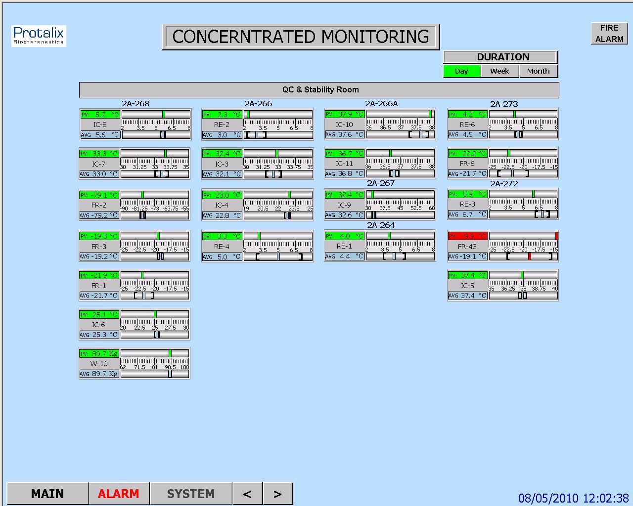
HMI Screen Test Procedure – intended to verify that the HMI screens provide the graphic design and functionality required for properly monitoring and controlling the environmental conditions in the user's

Parameters Lists Verification – intended to verify that the system parameters lists comply with the values specified in the SSO

Two types of parameters are checked

Process parameters

Alarm parameters

System Operation Test Procedure – intended to verify that system monitoring and control components are capable of maintaining the user's facility within specified temperature, humidity and pressure levels

System Alarms Test Procedure – intended to verify that when the specified temperature, humidity and pressure levels exceed its specified limits, an alarm message is displayed, and an SMS or e-mail notification is sent to relevant personnel

Test of HMI Compliance with 21 CFR Part 11 – This test is intended to verify that the HMI meets Valtech Cardio's URS regarding 21 CFR Part 11. These : requirements are divided into 5 categories for the sake of clarity

Security

Electronic Records

Audit Trail

Archive

Backup

 HMI Screen Test Procedure

This section includes specific test procedures for all the relevant HMI screens, where each test procedure serves to verify that the specific HMI screen provides the graphic design and functionality required for its intended purpose within the monitoring and controlling functions

Parameters Lists Verification

:This procedure covers the verifications of two types of parameters

Process parameters

Alarm parameters

Process Parameters List Verification

This procedure is intended to verify that:

The system enables to set the default values of the process set-points of each monitored environmental parameter.

The system provides automatically the corresponding low and high limits of these default values. These limit values are listed in  below

The system rejects all the SP values that exceed their allowed ranges, as specified in the SSO

Alarm Parameters List Verification

:This procedure is intended to verify that

The system enables to set the default values of the alarm set-points of each monitored environmental parameter

The system provides automatically the corresponding low and high limits of these default values

The system rejects all the SP values that exceed their allowed ranges, as specified in the SSO

 System Operation Test Procedure

This procedure is intended to verify that system monitoring and control components are capable of maintaining the user's facility within specified temperature, humidity and pressure levels. For this purpose, it is necessary to temporarily change set-points, in order to activate the control devices

System Alarms Test Procedures

This procedure is intended to verify that, when an environmental parameter value exceeds the specified normal range, the system reacts as specified in the SSO, by providing a specified alarm indication, a relevant e-mail alarm message, and relevant records in the Current Alarms and Historical Alarms screens

Test of HMI Compliance with 21 CFR Part 11

This test is intended to verify that the HMI meets the user's URS regarding 21 CFR Part 11. These requirements are divided into 5 categories for the sake of :clarity

Security

Electronic Records

Audit Trail

Archive

Backup


ולידציה – Operation Qualification – OQ- part 1

ולידציה – Operation Qualification – OQ- part 1

Protocol Preparation Overview

The Operation Qualification (OQ) protocol is part of the validation documentation that covers the verification of the proper operation of the system under validation in the user's facility. This OQ protocol is generic, and the system may include a PC with Human/Machine Interface (HMI), a Programmable Logic Controller* (PLC), pressure, temperature and humidity transmitters, and other monitoring and control components designed to maintain the user's facility in proper environmental conditions (temperature, pressure and humidity)

This OQ protocol is intended to verify that the system under validation operates according to the acceptance criteria specified in the Schedule of System Operation (SSO), and also meets the vendor's requirements and the user's specifications. It must be reviewed and approved prior to the OQ performance

OQ Protocol Contents

The OQ protocol is structured in a relatively standard fashion, with predetermined chapters and sections, where the final contents are tailored according to the type and size of the system under validation

:The chapters and sections of an OQ protocol are

Documents Verification – procedure intended to verify that all the documents required for performing the OQ procedure are approved and available

OQ Test Procedures – this is the main part of the protocol, and provides the description of the test procedures and the result tables for filling and approving the test results

: Note

As the final contents of the OQ protocol are tailored according to the type and size of the system under validation, and this document is generic, it covers test procedures that may not be necessary in small or simple systems

Documents Verification

:This procedure is intended to verify that all the documents required for performing the OQ procedure are approved and available. These documents are

Functional Requirements Specification (FRS)

Installation Qualification (IQ) Protocol

Piping and Instrumentation Drawing – P&ID

Input/Output (I/O) List

Schedule of System Operation (SSO)

OQ Test Procedures

This chapter contains all the test procedures or verification required to verify the system under validation is properly installed and can be properly operated according to the supplier's requirements and user's specifications

:Each test procedure or verification must include the same contents

Purpose or Objective

Procedure or Method

Acceptance Criteria

Test Results

*Here are some examples of the PLCs used by smartlogic: 6XV1830-0EH10, 6ES7131-4BF00-0AA0,6ES7193-4CA40-0AA0,6ES7134-4GD00-0AB0,6ES7193-4CA40-0AA0, 6ES7138-4CA01-0AA0,6ES7193-4CC20-0AA0, 6ES7590-1AB60-0AA0, 6ES7511-1AK00-0AB0, 6ES7954-8LP01-0AA0,6ES7155-6AU00-0BN0

ולידציה -Testing Process Automation Systems

ולידציה – Testing Process Automation Systems  

 Testing Responsibilities  Supplier and User

Where a Supplier has been assessed and its quality management system found to be acceptable, the User may benefit from the testing already carried out as part of the product development life cycle in order to minimize additional testing.

Similarly, the User may benefit from the testing carried out by the Supplier as part of the application, for example, to allow a small sample of tests to be repeated at witnessed FAT.

                        Example of Life Cycle for a Custom Application

Supplier Product Life Cycle

For example in a life cycle where a new application is developed for an embedded control system,  the Supplier's product may be SW or tools used to develop the User specific application. The Supplier of the control system has been assessed and its quality management system found to be acceptable. Thus, the User does not need to repeat the testing of product functionality. The testing should instead concentrate on the application of the control system

     End User Application Life Cycle

Assuming that the application is critical to product quality and includes a custom sequence coded as a sequence function chart, a test approach could be agreed :that includes the following elements

Supplier's module testing of the sequence function chart program.

Supplier's integration testing (100% test) and FAT (sampled) to demonstrate correct interaction configuration of the control system and correct operation of the process equipment.

SAT and IQ/OQ/PQ of the control system as part of the process equipment.

                      Example of Life Cycle for a Standard Application

                   Supplier Product Life Cycle

In the case  of a life cycle where a standard application is purchased containing an embedded control system, the control system Supplier has been assessed and its quality management system found to be acceptable. Thus, the User does not need to repeat the testing of product functionality (including mature library functions such as standard control modules) or of the standard application. The testing has to cover only the setup and use of the application.

                    End User Application Life Cycle

Assuming that the application is still critical to product quality, there is now much lower risk associated with the application development, as the configuration is limited to selecting the required functions and entering setup parameters. A test approach could, therefore, be agreed including the following elements:

FAT to demonstrate correct setup of the control system and correct operation of the process equipment.

SAT and IQ/OQ/PQ of the control system as part of the process equipment.

ולידציה – GAMP – Test Example – part 3

Good Automated Manufacturing Practice (GAMP) – Test Example

Testing Process Automation Systems

This article cover  the third part of  our  Good Automated Manufacturing Practice (GAMP) test example. This part will cover  the typical test phases for Factory Acceptance Test – FAT, Site Acceptance Test – SAT / Installation Qualification – IQ, Operation Qualification – OQ and Performance Qualification – PQ

Typical Test Phases – GAMP – Test Example

 Typical test phases for a complex process automation system. This example assumes that the system is configured by a Supplier and delivered to site after a FAT. Test system can also be configured by the system integrator or by the User. In this case, the same coverage is required, but the test phasing and location may be different.

The User and Supplier should work together to develop an overall approach to testing that reflects the risk assessment output and ensures adequate test coverage of the functionality, whilst avoiding unnecessary repeated tests.

Factory Acceptance Test – FAT

Done at the Supplier's premises after Supplier's integration testing, and before the system is released for delivery to the User's site

The required coverage should reflect the relative risk priority associated with the system element under test. This coverage can increase if problem are found within the initial sample.

In determining the required coverage, the User needs to base decisions on the risk assessment output taking into account both the potential effect on product quality and safety resulting from the process, and the intrinsic risk likelihood associated with the method of implementation.

Before performing risk assessment to decide on the required coverage, the User should review the supplier's internal tests to confirm that they are adequately documented.

Site Acceptance Test – SAT / Installation Qualification – IQ

Done at the User's premises after installation of the system on site

:The required coverage should include

Checking that the full system, including HW, SW backups, and documentation has been delivered to site in a condition suitable to its intended purpose

Checking that the site environment suits the specification of the installed equipment: temperature, humidity, pressure, dust, vibration, interference, etc

Checking that the system has been correctly installed.

Demonstration the system still operates as it was when accepted during the FAT, typically by re-recording system components and versions, and by re-repeating a small sample of FATs on site

Testing any elements which could be adequately tested in the FAT environment, typically interfaces to other equipment, networks, etc

Re-testing, following remedial action on any element subject to conditional release at the end of the FAT

Operation Qualification – OQ and Performance Qualification – PQ

Done at the User's premises after SAT/IQ

If a system has been fully tested in the FAT, after successful completion of the IQ (along with any additional field functional tests and calibrations), the system is treated as an integrated part of the process equipment qualification. This should ensure that the full system, procedures and trained personnel are ready for production.

End of GAMP – Test Example – part 3.


ולידציה – GAMP – Test Example – part 2

Good Automated Manufacturing Practice (GAMP) – Test Example

Testing Process Automation Systems

This article cover  the second part of  our  Good Automated Manufacturing Practice (GAMP) test example. This part will cover  the typical test phases for supplier's application SW Module Testing, supplier's Module Integration Testing and the supplier's Integration Testing – cont'd

                     Typical Test Phases

 Typical test phases for a complex process automation system. This example assumes that the system is configured by a Supplier and delivered to site after a FAT. Test system can also be configured by the system integrator or by the User. In this case, the same coverage is required, but the test phasing and location may be different.

The User and Supplier should work together to develop an overall approach to testing that reflects the risk assessment output and ensures adequate test coverage of the functionality, whilst avoiding unnecessary repeated tests.

: Typical Test Phases for Process Automation Systems

 Supplier's Application SW Module Testing

Done at the Supplier's premises after the module has been placed under configuration control and code reviewed. Before system integration. Module testing generally covers: Module data handling

 Interfaces to other modules

 Operator interfaces

 Module functionality Failure paths and response to fault conditions should be included within the tests

Supplier's Module Integration Testing

Done at the Supplier's premises.After individual module have been tested and integrated into a single unit.Before full system integration

Module integration testing generally covers: Correct operation of Interfaces between modules

Failure paths and response to fault conditions should be included within the tests

Supplier's Integration Testing –

Done at the Supplier's premises.After module testing, and before the User is invited to witness the FAT

Integration testing generally covers:

 HW

I/O interfaces

Operator interfaces

Interfaces to other equipment

System functionality

Data handling functions

Failure paths and response to fault conditions should be included within the tests

:HW tests typically include

·      Checking system build against approved HW specifications and drawings

·      Recording system components, version numbers (including SW versions) and capacities

·      Checking electrical supplies and grounding

Supplier's Integration Testing (cont'd) –

Checking correct power up of system components

Checking any self test/diagnostic information

Checking correct communication on standard interfaces

:I/O interface tests typically include

Exercising inputs and outputs to check correct configuration of ranges, alarms, etc.

:Operator interface tests typically include

System displays and navigation

Security and access controls

:Tests for interfaces to other equipment typically include

Checks of communications protocol setup

Checks that the required data can be transferred

Checks of actions in case of communications failure

Tests for system functionality typically include:

Monitoring functions

Alarm strategies

Control functions)control modules, equipment modules, procedural control(

Power failure and recovery

Component failure and redundancy

Performance checks

:Tests for system data handling typically include

Operator data entry

Data formatting and quality checks

Checks of calculated values

Checks of recipes

Checks of access to current process data, alarms and events )displays, alarm summaries, etc.(

Checks of access to historical process data, alarms and events )trends, reports, alarm histories, etc.(

Checks of audit trail functionality

Checks of data capacity and retention times

Checks of archive and restore

Checks of provisions for electronic signatures

Checks of disaster recovery procedures

End of  ולידציה – GAMP – Test Example – part 2


ולידציה – GAMP – Test Example – part 1

Good Automated Manufacturing Practice (GAMP) – Test Example

Testing Process Automation Systems

This article cover  the first part of  our  Good Automated Manufacturing Practice (GAMP) test example.

                                     Definitions

This section provides brief descriptions of three different types of process control systems.

                  Configurable Equipment

Configurable Equipment is the collective name given to simple configurable instruments/ devices, such as 3-term controllers, check scales, bar code readers, etc. Their functionality depends on that their configuration setup meets the process requirements. The software (SW) components of these systems are typically defined as GAMP SW Category 2.

                    Embedded Systems

Embedded Systems is the collective name for systems with a greater degree of configuration and programmability. Devices such as Integrated Circuits (ICs) with configuration setups and Programmable Logic Controllers (PLCs), which are supplied as an integral part to an item of process equipment, e.g., PLCs controlling a centrifuge or packaging machine, or IC embedded in High Performance Liquid Chromatography (HPLC) systems. Embedded Systems typically contain SW components belonging to multiple GAMP categories.

                 Stand-Alone Systems

Stand-Alone Systems is the collective name for large programmable control systems having distributed functionality across a network, e.g., Distributed Control Systems (DCSs), and Supervisory Control and Data Acquisition (SCADA). They are engineered as an entity to control a complete plant. Stand-Alone Systems typically contain SW components belonging to multiple GAMP categories.

                      Testing and the GAMP Life Cycle 

     Stand-Alone Systems

A process automation system developed for a new application typically requires some or all of the following test phases:

Suppliers Module Testing

Suppliers Module Integration Testing

Suppliers Integration Testing

Factory Acceptance Test (FAT)

Site Acceptance Test (SAT)

Installation Qualification (IQ)

Operation Qualification (OQ)

Performance Qualification (PQ)

The exact combination of testing required for a particular system should reflect its complexity, the maturity of its underlying SW and hardware (HW) elements, and the risk impact on product quality, patient safety and data integrity. Collectively these will determine the risk priority. The phrase 'low risk' should be understood as 'having a low risk priority, as determined by a formal risk assessment'.

Testing of modifications, patches or upgrades should be related to the risk priority of the change. For example, it may be appropriate for parameter changes to be applied directly to the production environment, assuming that the system have been range checked for such parameter.

End of ולידציה – GAMP – Test Example – part 1

ולידציה – Installation Qualification (IQ) Protocol – 2

Installation Qualification (IQ) Protocol

Preparation Overview – part 2

 Installation Qualification (IQ) Protocol –  Test Procedures

This chapter contains all the test procedures or verifications required to verify the system under validation is properly installed and can be properly operated according to the supplier's requirements and user's specifications.

Each test procedure or verification must include the same contents:

Purpose or Objective

Procedure or Method

Acceptance Criteria

Test Results

The next sections provide overviews of the main test procedures and verifications, and their purposes. This IQ procedure is generic, and relevance of the test procedures and verifications provided below depends on the composition of the system under validation.

Note:

As mentioned in the previous chapter on IQ Protocol Contents, the final contents of the IQ protocol are tailored according to the type and size of the system under validation. Since this document is generic, it covers test procedures that may not be necessary in small or simple systems.

Drawings Verification

This procedure is intended to obtain signed, updated copy of the user's Piping and Instrumentation Drawing (P&ID), and verify that the drawing is accurate.

 Site Preparations

This procedure is intended to verify that the system under validation is installed and operated under environmental conditions, in particular temperature conditions, which comply with the manufacturer’s requirements.

                          Hardware Installation Test Procedures

  Voltage Supply

This procedure is intended to verify that the voltage supplied to the system components complies with the design requirements.

 IO List

This procedure is intended to verify that the system components are identified and installed in compliance with the IO List, the P&ID, and the system hardware requirements.

                        Software Installation Test Procedures

This section describes the test procedures for the installation of purchased software (SW) and application SW. These test procedures are relevant when the supplier installs these SW systems.

Supplier Installed Software

This procedure is intended to verify that purchased SW installed in the supervisory computer and control system (where relevant) by the supplier complies with the SW design requirements.

 Other Purchased Software

This procedure is intended to verify that other purchased SW, such as a version of Windows, is correctly installed on the system.

  Application Software

This procedure is intended to verify that the custom application SW is installed according to the design requirements.

 Closed System Verification (Where Relevant)

This procedure is intended to verify that the system is closed, i.e., it cannot communicate with Internet networks.

Glossary

CFR Code of Federal Regulations
FDA Food and Drug Administration
FRS Functional Requirements Specification
HW Hardware
IQ Installation Qualification
OQ Operational Qualification
QA Quality Assurance
SSO Schedule of System Operation
SW Software
URS User Requirements Specification

ולידציה – Installation Qualification (IQ) Protocol

ולידציה – Installation Qualification (IQ) Protocol

Preparation Overview – part 1

The Installation Qualification (IQ) protocol is part of the validation documentation that covers the verification of the proper installation and operation of the system under validation in the user's facility. This IQ protocol is generic, and the system may include a PC with Human/Machine Interface (HMI), a Programmable Logic Controller (PLC), pressure, temperature and humidity transmitters, and other monitoring and control components designed to maintain the user's facility in proper environmental conditions.

The IQ protocol is designed to verify that the system under validation is properly installed and can be properly operated according to the supplier's requirements and the user's specifications. It must be reviewed and approved prior to the IQ performance.

                            Installation Qualification (IQ) Protocol Contents

The IQ protocol is structured in a relatively standard fashion, with predetermined chapters and sections, where the final contents are tailored according to the type and size of the system under validation.

:The IQ protocol includes the following chapters and sections

 Document Approvals – contains a table that lists the supplier's and user's personnel required to approve the protocol

Participants – contains a table with the supplier's and user's personnel that participate in the validation process and approve their participation

Responsibilities – lists the roles of supplier's and user's personnel responsible for writing and approving the protocol

Glossary – lists the acronyms used in the protocol

IQ Validation Approach – defines the scope of the IQ process, and the requirements for its successful completion

IQ Test Procedures – this is the main part of the protocol, and provides the description of the test procedures and the result tables for filling and approving the test results

IQ Approvals – contains a table with the user's personnel responsible for reviewing and approving the test results, summary reports and conclusions

Appendices – include validation deviation forms and the documentation list with all the documents and drawings relevant to the IQ process

This is the first part of  the preparation overview in Installation Qualification (IQ) protocol, the second part is  IQ Test Procedures which will be discus elaborately in our next article.

ולידציה – ספציפיקציה פונקציונלית

ולידציה – ספציפיקציה פונקציונלית (Functional Specification)

ספציפיקציה פונקציונלית (Functional Specification) (שנקראת לפעמים ספציפיקציות פונקציונליות) היא מסמך פורמלי שמשמש לתיאור מדויק, עבור מפתחי התוכנה, את היכולות, המראה והאינטראקציה עם המשתמשים הנדרשים מהמוצר. הספציפיקציה הפונקציונלית היא סוג של קו מנחה ובהמשך נקודת יחוס עבור המפתחים שכותבים את קוד התוכנה. (לפחות קבוצת פיתוח אחת של מוצר עיקרי השתמשה בגישה "התחל מכתיבת המדריך". לפני  קיום המוצר, המפתחים כתבו מדריך למשתמש עבור מערכת עיבוד האות, ואח"כ הצהירו שמדריך זה היה הספציפיקציה פונקציונלית.  המפתחים אותגרו לפתח מוצר שיתאים לתיאורים שהופיעו במדריך למשתמש). בצורה אופיינית, הספציפיקציה הפונקציונלית לתוכנית אפליקציה עם סדרה של חלונות אינטראקטיביות ודיאלוגים עם המשתמש אמורה להראות את הצורה הוויזואלית של ממשק המשתמש, ולתאר כ"א מפעילויות הכניסה האפשריות של המשתמש ופעילויות התגובה של התוכנית. הספציפיקציה הפונקציונלית יכולה גם לכלול תיאורים פורמליים של מטלות המשתמש, תלות במוצרים אחרים, וקריטריונים לשימוש. לחברות רבות יש מדריך למפתחים שמתאר איזה נושאים צריכים להיכלל  בספציפיקציה הפונקציונלית של כל מוצר.

כדי להמחיש את הצורה שבה הספציפיקציה הפונקציונלית משתלבת בתהליך הפיתוח, להלן סדרה אופיינית של צעדים שצריכים להיכלל בפיתוח מוצר תוכנה:

  • דרישות: זו הצהרה פורמלית של מה שמתכנני המוצר, לפי ידיעתם על המצב בשוק ומידע ספציפי על של לקוחות קיימים או פוטנציאליים, מאמינים לגבי התכונות הנדרשות למוצר חדש או לוורסיה חדשה של מוצר קיים. דרישות אלו מוצגות בד"כ באופן יחסית כללי.
  • מטרות: המטרות כתובות ע"י מתכנני המוצר בתגובה לדרישות. הן מתארות באופן יותר ספציפי את תכונות המוצר. המטרות יכולות לתאר את האדריכלות, פרוטוקולים וסטנדרטים שאליהם המוצר חייב להתאים.  מטרות שניתנות למדידה הן אלו שקובעות קריטריונים שלפיהם ניתן להעריך את המוצר הסופי.  אפשרות למדידה ניתנת לביטוי במונחי אינדקס של שביעות רצון הלקוח או במונחים של יכולות וזמני ביצוע. לצורך עמידה במטרות, חייבים לקחת בחשבון את מגבלות הזמן והמשאבים. לו"ז הפיתוח הוא בד"כ חלק או מסקנות מהמטרות.
  • ספציפיקציה פונקציונלית: ספציפיקציה פונקציונלית היא התגובה הפורמלית למטרות. היא מתארת את כל ממשקי המשתמש החיצוני והתוכנה שבהם המוצר חייב לתמוך.
  • בקשות לשינוי עיצוב: במשך תהליך הפיתוח, כאשר מופיע צורך לשינוי הספציפיקציה הפונקציונלית , שינוי פורמלי מתואר בבקשה לשינוי עיצוב.
  • ספציפיקציה לוגית: מבנה התוכנה (לדוגמה, קבוצות עיקריות של מודולי קוד שתומכים בפונקציה דומה), מודולי קוד אינדיבידואלים והיחס ביניהם, ופרמטרים של נתונים שהם מעבירים ביניהם ניתנים לתיאור במסמך פורמלי שנקרא ספציפיקציה לוגית. מסמך זה מתאר את הממשקים הפנימיים, ומשתמשים בו רק המפתחים, בקרים, ובהמשך, במידה מסוימת, המתכנתים שעוסקים במוצר ומספקים תיקוני קוד לשדות.
  • תיעוד למשתמש: באופן כללי, כל המסמכים הקודמים (חוץ מהספציפיקציה הלוגית) משמשים כחומר מקור עבור המדריכים הטכניים והמידע המקוון (online) (כגון דפי עזר) שמכינים עבור המשתמשים במוצר.
  • תכנית בדיקה: לרוב קבוצות הפיתוח יש תכנית בדיקה פורמלית שמתארת דוגמאות בדיקה לצורך תרגול עם התוכנה שנכתבה. הבדיקה נערכת ברמת מודול (או יחידה), ברמת רכיב, וברמת מערכת בהקשר עם מוצרים אחרים. ניתן להתייחס לבדיקה כזו כ לבדיקת alpha. התכנית יכולה לאפשר גם בדיקת beta. חברות מסוימות מספקות וורסיה מוקדמת של המוצר לקבוצה נבחרת של לקוחות לצורך בדיקה "בעולם האמיתי".
  • המוצר הסופי: באופן אידאלי, המוצר הסופי הוד יישום מלא של הספציפיקציה הפונקציונלית והבקשות לשינוי עיצוב, שחלקם יכולות לנבוע מבדיקה פורמלית ובדיקת beta.

סדרת צעדים זו יכולה לחזור על עצמה בוורסיה הבאה של המוצר, החל מהצהרת הדרישות, שבאופן אידאלי מתייחסת למשוב חוזר מהלקוחות לגבי המוצר בשימוש, להחלטה על הצורך או רצון הלקוחות בהמשך.

רוב כותבי התוכנה דבקים לתהליך פיתוח פורמלי דומה לזה המתואר מעל. תהליך פיתוח החומרה דומה, אך מכיל שיקולים נוספים לביצוע מיקור חוץ ווידוא לתהליך היצור עצמו.

לפירוט נוסף בנושא  תוכנה מומלץ לקרוא גם את ולידציההבטחת איכות תוכנה – QA


ולידציה – GAMP – Test Environments – Test Data Sets

ולידציה  Good Automated Manufacturing Practice – GAMP – Test Environments – Test Data Sets

Test data sets are often use where the test environment does no permit the use of real data for reasons of availability or confidentiality, or where the real data are not generic enough to cover certain test types (e.g., challenge testing at boundary conditions or stress testing).

                          Representative Test Environment

Test data should represent as close as possible the actual data to be operated on, in terms of volume and range of possible values (including invalid entries, to check that they can be correctly handled).

Differences between the proposed test data and the expected actual data should be detailed on the Test Specification or Protocol, and subject to impact assessment. If necessary, additional tests should be planned for the production environment in order to cover identified risk scenarios.

                         Control of Test Environment

Test data sets should be placed under configuration management and the version in use recorded.

For automatically generated data it may also be appropriate to control the utility used for generating the data, as well as the test data set

                         Removal from Production Environment

If the test data SW is added in the way that it may appear in the production environment, then, this should be documented a temporary modification to the production system. Removal of the temporary modification should be documented as well.

If the production environment includes automatic audit trailing, then it should be recognized that all audit trail entries from the testing process will remain.

                              Test User Accounts

Test user accounts are often used to permit testers to access the system at different levels, and ensure that activities carried out during testing are easily identified within any resulting audit trail.

                          Representative Test Environment

Where test user accounts are often used, these should be set up to represent each group of users within the system, including the corresponding authorizations. For multi-lingual system, test user accounts using foreign character sets should be included. Similarly, if existing individual accounts are used for testing, representatives from each group should be included.

                         Control of Test Environment

If test user accounts are used, then the setup of the accounts should be retained as part of the test documentation. Where there are issues of data confidentiality, controls should be exercised to ensure that the use of test accounts does not cause breaches of confidentiality.

                        Removal from Production Environment

If the test user accounts are added in the way that it may appear in the production environment, then, this should be documented a temporary modification to the production system. Removal of the temporary modification should be documented as well.

                            Test Documentation

The test environment includes documentation used during testing. This should always include the test documentation (Test Plans and Strategies, Protocols and Test Specifications, Test Cases and Test Scripts) and the controlling Design Specifications. It may also include operating procedures such as SOPs.

The test documentation should be controlled and recorded to a level of detail that would allow it to be retrieved as part of later review of the test results. This control would, at minimum, include the recording of current document version levels.