Smartlogic

בקרה ואוטומציה, כל מה שרצית לדעת מהיסודות

סרטון הסבר- רקע על מערכות בקרה ואוטומציה לתעשייה 

מערכת בקרה הינה מערכת אוטומטית ששולטת על ציוד המתקן.

מערכת בקרה בצורת PLC- בקר מתוכנת – עם כניסות ויציאות אלקטרומכאניות.

הבקר מאפשר שליטה אוטומטית על מערכות שבעבר היו ידניות, כגון: ברזים, מערכות אוורור, וכו.

עוד תוכלו ללמוד בסרטון: 

  • מה זה תפ"מ
  • מה התפקיד של בקר PLC במערכת ואיך הוא עובד 
  • כרטיסי הרחבה לבקר 
  • ממה מורכבת מערכת בקרה ומה הן כוללות (עבודה עם רגשים, מנועים )
  • עבודה עם remote I/O –  באתרים גדולים

מציג: מר אילן שעיה,מומחה בקרה ומנכ"ל חברת סמארט לוג'יק


אוטומציה ובקרה

מהי אוטומציה ובקרה?

מאמר זה מספק הגדרה מקצועית למונח אוטומציה ובקרה, מונה רכיבים הנכללים במערכות בקרה ואוטומציה ומציג אספקטים רלוונטיים נוספים לנושא הנידון.

הגדרת המונח פיתוח אוטומציה ובקרה

המונח אוטומציה – Automation מתאר שימוש במכונות, מערכות בקרה וטכנולוגית מידע (Information Technology – IT) כדי להפיק את המרב בתהליכי יצור ואספקת שירותים.

יתרונות וחסרונות

היתרונות העיקריים של אוטומציה הם:

  • הגברת התפוקה או פרודוקטיביות.
  • שיפור האיכות והגדלת יכולת חיזוי האיכות.
  • שיפור אחידות התהליכים והמוצרים.

בד"כ מתקינים ומשתמשים באוטומציה במקרים הבאים:

  • בתהליכי יצור לקיצור זמן המחזור, ושיפור התפוקה, האיכות והאחידות.
  • בתהליכים שמצריכים דרגת דיוק גבוהה.
  • מילוי מקום של עובדים בפעילויות שמצריכות כוח פיזי או פעילות מונוטונית.
  • מילוי מקום של עובדים בתנאי סיכון (כגון סכנת בערה, עבודה בחלל, עבודה תת-מימית וכו').
  • בביצוע פעילויות מעבר ליכולת האנושית מבחינת גודל, משקל, מהירות, כוח סבל וכו'.
  • יתרון כלכלי – אוטומציה יכולה לשפר את כלכלת מיזמים וחברות.
  • שחרור עובדים למילוי תפקידים אחרים.
  • אספקת עבודות ברמה גבוהה יותר בתכנון, פריסה, התקנה, הפעלה ותחזוקה של ציוד אוטומטי.

החסרונות העיקריים של אוטומציה הם:

  • סיכון ו/או פגיעות בבטיחות התהליכים – למערכת אוטומטית רמה מוגבלת של אינטליגנציה, ולכן היא יותר רגישה לביצוע שגיאות.
  • הוצאות פיתוח בלתי צפויות – הוצאות המחקר ופיתוח של אוטומציית תהליך יכולות להיות גדולות יותר מהחסכונות המופקים מהמערכת האוטומטית המושגת.
  • הוצאות התחלתיות גבוהות – אוטומציה של תהליך יצור או מתקן מצריך השקעה התחלתית עצומה בהשוואה למחיר היחידתי של המוצר, למרות שמחיר האוטומציה מתחלק בין מספר רב של מוצרים.

 מגבלות

  • הטכנולוגיה במצבה הנוכחי לא מאפשרת אוטומציה ובקרה של כל הפעילויות הרצויות.
  • כאשר רמת האוטומציה של תהליך הולך גדל, כמות העבודה שנחסכת והשיפור ברמת האיכות פוחתים, ואיתם הכדאיות הכלכלית.


הגדרת המונח בקרה אוטומטית

מתייחסת לשימוש בתיאורית הבקרה לוויסות תהליכים או תנאים ללא התערבות ישירה של בן אדם. בצורה הפשוטה ביותר של מעגל בקרה אוטומטי, בקר משווה ערך נמדד בתוך תהליך עם ערך מתוך סדרת ערכים שנקבעה מראש, ומעבד את אות הסטייה שנוצרה כך שהתהליך נשאר במסגרת הערך שנקבע למרות ההפרעות.

רכיבים של מערכת בקרה אוטומטית

מושג עיקרי בבקרה אוטומטית הוא מערכת בקרה אוטומטית, שמספקת בקרה וניטור של סוגים שונים של מערכות רלוונטיות, כגון ייצור, ניהול, וכו'. לדוגמה, אפשר לתכנן מערכת בקרה לשימור גבולות מוגדרים של ערכי טמפרטורה, לחץ ולחות בתוך מתקן ייצור.

מערכת בקרה מורכבת ממגוון רכיבים מבוקרים, ומשוב (feedback) של נתוני בקרה ממכשירי מדידה במעגל סגור (closed loop), שמאפשרים פעולה נכונה של רכיבי המערכת (כגון אלו הרשומים בהמשך) בהתאם לערכים שנקבעו מראש:

  • רגשים (sensors), שמודדים תנאים פיסיקליים, כגון טמפרטורה, לחץ, גובה נוזל, וכו'.
  • בקרים (controllers), שיכולים להיות החל מרכיבים פיסיקליים פשוטים ועד בקרים דיגיטליים מורכבים או מחשבים משובצים (embedded).
  • מפעילים (actuators), שמגיבים למדידות הרגשים ופועלים בהתאם להוראות הבקרים; לדוגמה, בבקרת כניסת אנרגיה, כגון, זרימת גז למבער במערכת חימום, או חשמל למנוע במקרר, או משאבה.
  • תחנת/ות מחשב, שמקושרות לבקרים. המחשבים משמשים להצגת ערכים נמדדים שהתקבלו מהבקרים במסכים של ממשק אדם/מכונה (HMI – Human/Machine Interface), ולשנות ערכים נקבעים (settings), כדי לאפשר ניטור ובקרה עכשוויים (online) של המערכת ע"י המשתמשים.

 רגשים (Sensors)

רגשים, שמודדים תנאים פיסיקליים, כוללים בד"כ אמצעים לשדר את הערכים שהם מודדים ל בקרים המתאימים; במקרה זה הם גם נקראים משדרים (transmitters). הם יכולים לכלול בנוסף מצגות ערכים (indicators) לפיקוח ויזואלי קל ע"י המשתמש.

בקרים (Controllers)

הבקרים הם הרכיבים החשובים ביותר במערכת בקרה אוטומטית. הם יכולים להיות החל מרכיבים פיסיקליים פשוטים ועד בקרים דיגיטליים מורכבים או מחשבים משובצים. הבקרים מנתחים ומעבדים את הערכים הנמדדים ע"י הרגשים ושולטים על המערכת בהתאם, בצירוף עם מחשבים מחוברים לבקרים; המחשבים כוללים תוכנות HMI לניטור ובקרה של המערכת.

דוגמאות של בקרים:

  •  בקרים לוגיים שניתנים לתכנות (PLCs – Programmable Logic Controllers)*
  • בקרים דיגיטליים ישירים (DDCs – Direct Digital Controllers)
  • יחידות קצה רחוקות (RTUs – Remote Terminal Units)

מפעילים (Actuators)

המפעילים מגיבים למדידות הרגשים ופועלים בהתאם להוראות הבקרים. דוגמאות של המפעילים הם: מתגים המגיבים להפרשי לחץ (DPSs – Differential Pressure Switches), מרסני נפח ממונעים (MVDs – Motorized Volume Dampers), מקררים ותנורים חשמליים, וכן משאבות ומפוחים, שמאפשרים כיוונוני טמפרטורה, לחץ, לחות, ותנאים פיסיקליים אחרים, כדי לתחום אותם בהתאם לערכים שנקבעו מראש.

תחנת/ות מחשב

תחנה מחשב אחת או יותר שמקושרות לבקרים מקבלות ערכים נמדדים מהבקרים ומציגים ערכים אלו, וכמו כן מצב פעולת רכיבי המערכת במסכים של ממשק  HMI לניטור עכשווי של המערכת. הערכים הנמדדים ניתנים להשוואה עם ערכים מותרים שנקבעו מראש, ואם הערכים הנמדדים חורגים מהגבולות המותרים, אפשר להציג הודעת אזהרה. ניתן להשתמש בממשק  HMI גם כדי לשנות את הערכים המותרים ולנטר את מצב פעולת רכיבי המערכת כתגובה לשינויים.

* סמארט לוג'יק משתמשת בבניית מערכות אוטומציה ובקרה בבקרים של חברת Siemens  וחברת אלן ברדלי – Allen-Bradley.

סמארטלוג'יק משווקת בין היתר את המוצרים הנ"ל:

6XV1830-0EH10, 6ES7131-4BF00-0AA0, 6ES7193-4CA40-0AA0, 6ES7134-4GD00-0AB0, 6ES7193-4CA40-0AA0, 6ES7138-4CA01-0AA0, 6ES7193-4CC20-0AA0, 6ES7590-1AB60-0AA0, 6ES7511-1AK00-0AB0, 6ES7954-8LP01-0AA0, 6ES7155-6AU00-0BN0, 1746-NO4V, 1769-L16ER-BB1B.


ממשק אדם-מכונה HMI – אוטומציה ובקרה

מה זה HMI?

ממשק אדם-מכונה Human-Machine Interface – HMI מתרחש בתחום בו חלה אינטראקציה בן בני אדם ומכונות. מטרת האינטראקציה היא אפשרות  לניטור ובקרה יעילים של  אותן מכונות ע"י מפעיליהן, כאשר המכונות מספקות מידע בהיזון חוזר שמאפשר למפעילים לקחת החלטות נכונות בזמן התהליך. לממשק זה יש שימוש נרחב בעיצוב, יצור ובקרה על ציוד תעשייתי, ועל ניטור ובקרה על תהליכים תעשייתיים.

עם השימוש הגדל במחשבים אישיים ובקרים ממוחשביםProgrammable Logic Controller – PLC, הפך HMI למונח  המתייחס לרוב לייצוג הגרפי של הציוד והתהליכים התעשייתיים על פני מסכי המחשבים.

סמארטלוג'יק משתמשת ב -PLCs מתוצרת סימנס (Siemens) ואלן ברדלי (Allen Bradley)  לדוגמא :

6XV1830-0EH10, 6ES7131-4BF00-0AA0,6ES7193-4CA40-0AA0,6ES7134-4GD00-0AB0,6ES7193-4CA40-0AA0, 6ES7138-4CA01-0AA0,6ES7193-4CC20-0AA0, 6ES7590-1AB60-0AA0, 6ES7511-1AK00-0AB0, 6ES7954-8LP01-0AA0,6ES7155-6AU00-0BN0

מונח אחר, פחות שימושי הוא ממשק איש-מכונה הוא  Man-Machine Interface – HMI. מונח זה היה נפוץ אך זכה להתרעמות מצד ארגוני הנשים שדיברו על כך שגם נשים הם משתמשות בממשקים אלו ומהוות חלק מהם כך שונה השם למונח הכללי אדם או באנגלית Human.

HMI מערב ציוד (חומרה) היקפי, ורכיבי תוכנה, כגון ממשקים גרפיים.

בתחום המקושר ל- HMI, שנקרא Human-Computer Interaction – HCI, חוקרים את הייצוב והשימוש בטכנולוגיית המחשב, תוך מיקוד מיוחד בממשקים בין אנשים ומחשבים. החוקרים בתחום זה מתבוננים בצורות שבהם אנשים פועלים מול מחשבים, ומעצבים טכנולוגיות  שמאפשרות אינטראקציה  בין אנשים ומחשבים באופנים חדשים.

אנשים  פועלים מול מחשבים בצורות שונות, והממשק בו משתמשים משחק תפקיד מכריע בהקלה באינטראקציה. אפליקציות במחשב שולחני, דפדפן (browser) אינטרנטי,  מחשבים נישאים, וכו', משתמשות בממשק לשימוש גרפי Graphical User Interface – GUI באופן הנפוץ ביותר; ממשק לשימוש קולי Voice User Interface – VUI, פחות נפוץ, משמש לזיהוי דיבור ומערכות סינתוז synthesizing. השימוש ב- multi-modal GUI מאפשר להשתלב עם גורמים מסוימים שלא ניתנים  לתקשורת עם כלי ממשק אחרים.

שימוש ב-HMI לצורכי בקרה ואוטומציה

בתחום הבקרה והאוטומציה אנו עוסקים רבות בממשק Human-Machine Interface – HMI בעת תכנון ותפעול מערכות בקרה תעשייתיות.

תכנון וביצוע פרויקטים הנדסיים בתחום הבקרה האוטומציה היא המומחיות של סמארטלוג'יק, בקרה מפעלית ובקרות תהליך, בקרות מבנה BMS.  שיטות עבודה שלנו מאפשרות ביצוע אינטגרציה במהירות שיא, בין פרויקט חדש ומערכות המפעל הקיימות. סמארטלוג'יק מבצעת פרויקטי אוטומציה ובקרה מודולארית למתקני יצור תוך שימוש בתקן S-88.  סמארטלוג'יק היא גם  נציגה בלעדית של Siemens בארץ לתמיכה במערכת PCS7 ועובדת על בסיס קבוע, עם מרכז התמיכה העולמי בגרמניה באמצעות מערכת בקרת איכות מחמירה העומדת בתקן ISO9000.

להדרכה איך גורמים ל HMI לעבוד עם הרשאות ווינדוס לחצו כאן.

ולידציה – Function Design Specification – FDS

ולידציה – Function Design Specification – FDS

 This article was written by Iian Shaya, validation,automation and control expert

The Function Design Specification (FDS) is part of the validation documentation that details the solution to be provided to meet the user's requirements. It should be approved by the user and should form the basis of the design for both hardware (HW) and software (SW) designs.

The FDS provides the basis of the design of the system and is used to verify and validate the system during the testing, ensuring all the required functions are present and that they operate correctly. It details all the functions, operator interactions control and sequencing associated with the system, thus allowing the user to confirm, before the system is developed that the proposed solution fully meets its requirements.

FDS Contents

The FDS is structured in a relatively standard fashion, with predetermined chapters and sections, where the final contents are tailored according to the type and size of the system under validation. The FDS presented here includes only to the technical contents. It does not include commercial and contractual requirements, which may also be generally included.

The main chapters and sections of an FDS protocol are:

Relationship to Other Documents – lists all documentation used in the production of the FDS. Includes suppliers' documents (such as URS) and drawings. Each document listed should include the document/drawing number and version number. This allows traceability as documents are updated throughout the project life cycle on any impact on the FDS.

System Overview

Process Overview – includes a description of the process being controlled; this may be taken from the URS, enhancing to detail the interaction with the control system.

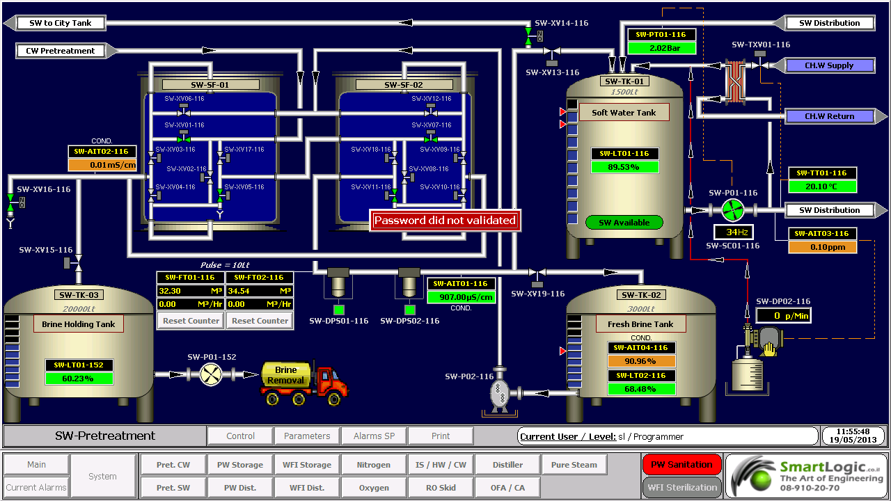
Control System Overview – includes detailed control system description, with all the components and interaction between the systems; block and network diagrams can be used to show in detail the system architecture

Scope and Limits of Supply

Scope of Supply – includes a list of deliverables, panels, computers, software, etc

Limits of Supply – includes all items outside the scope of the supply required by the project; where interfacing to 3rd party systems, constraints and assumptions should be included

System Functions and Facilities

Operation Modes – includes all modes of operation for the system

Functional Operation – divides each of the sequences functions into logical areas (determined by the process), and provide complete description of each area

Operator Requirements – describes the interface between the operator and the detailed function

Human/Machine Interface- HMI – details all points of operation, local terminals, remote terminal, message displays, push button stations, etc.

Report Outputs – the format of all reports generated by the system should be detailed, and that the format and explanation of the report contents should be included

System Data – all data gathered, generated or calculated by the system should be detailed

System Interfaces – provide complete details of all inputs and outputs from the control system

System Attributes

Availability – defines expected "working" time of the system between failures

Maintainability – details issues related to maintainability of the plant, in particular for systems that require regular maintenance to ensure the reliable operation

Transport and off loading

Power and services required

Connections to existing/3rd party systems

Changes to existing plant or hardware (HW) equipment

Changes to existing software (SW) systems

Training – details the formal and informal training to be supplied under the contract

Design Factors – details special factors relating to the design of the system, standards and methodologies to be followed for both the HW and SW development

Development Factors

Project Control – includes or makes reference to project plans and timescales, along with details of quality requirements, standards, test and integration and configuration management

Resource Requirements – includes the basic project team provided by the supplier, the access required to the customer's premises, and input and timing required by the customer into the project

Test procedures – including details of all test documentation and responsibilities for testing both offline and online

Module and Integration Testing

Factory Acceptance Testing (FAT) – performed at the suppliers premises

Site Acceptance Testing (SAT) – performed on completion of commissioning to demonstrate pre-handover system operation

:Note

As the final contents of the FDS are tailored according to the type and size of the system under validation, and this document is generic, it covers test procedures that may not be necessary in small or simple systems. The following sections cover the FDS issues that require further details

 About the system functions and facilities in our next article FSD System Function & Facilities

 This article was written by Iian Shaya, validation,automation and control expert

אילן שעיה ilan Shaya

אוטומציה ובקרה – PID Control

אוטומציה ובקרה – PID Control

Between the measuring device and the final control element comes the controller. Its function is to receive themeasured output signal Ym (t) and after comparing it with the set point YSP to produce the actuating signal c (t) in such a way as to return the out put to the desired value YSP. Therefore the input to the controller is the error ε(t) = YSP –Ym (t), while its out put is c (t). The various types of continous feedback controllers differ in the way they relate ε (t) and c (t).

 The best feed back controller is the proportional – integral- derivative controller.

In the industrial practice it is commonly known as the proportional-plus-reset-plus-rate controller.

The actuating signal of this controller is given by the following mathematical equation.

c (t) = Kc ε (t) + Kc/Ʈ10 t ε (t) dt + Kc ƮD dε/dt + Cs

Kc = proportional gain of the controller

Cs = controllers bias signal (i.e. its actuating signal when ε =0)

Ʈ1 = integral time constant OR reset time in minutes

TD = derivative time constant in minutes

Proportional = Kc ε (t)

Here the actuating out put c (t) is proportional to the error ε (t) = YSP –Ym (t),

It is clear that larger the gain Kc, the higher the sensitivity of controllers actuating signal to deviations (ε).

ie: Y SP =100, Ym(t) =96, hence error ε = 4.

If Kc=1, then controllers actuating signal, c = 4% to close/open, for TCV.

If Kc=3, then controllers actuating signal, c= 12% to close/open, for TCV

Integral = Kc/Ʈ10 t ε (t) dt

The reset time, Ʈ1 is the time needed by the controller to repeat the initial proportional action change in its out put. Reset time, Ʈ1 is an adjustable parameter and some manufacturers do not calibrate their controllers in terms of Ʈ1, but in terms of its reciprocals, 1/ Ʈ1 (repeats per minute), which is known as the reset rate.

ie:

Reset rate=0.1, it means the reset time is = 1/0.1= 10 scans, Hence every 10 scans the controller will add the proportional action change (Kc ε (t)).

In most of the PID's time scans is configurable and called "update loop time" if it equals to 1 then every 10 seconds the controller will add the proportional action

Remark:

The integral term of a controller causes its output to continue changing as long as there is a non-zero error. Often the errors cannot be eliminated quickly, and given enough time they produce larger and larger values for the integral term, which in turn keeps increasing the control action until it is saturated ( ie: the valve is completely open or closed) &  called as integral wind up.

Derivative = Kc ƮD dε/dt

ƮD is the derivative time constant in minutes, with the presence of the derivative term, (dε/dt), the PID controller anticipates what error will be in the immediate future and applies a control action which is proportional to the current rate of change in the error. Due to this property, the derivative control action is referred to as anticipatory control.

Because of the forecasting action of the derivative parameter, the control valve will never "rest" it will always open and close to maintain the Setpoint therefore – this parameter must be used only for fast PID's such as compressed air control, Steam control, ETC

אילן שעיה Ilan Shaya 

,This guide was written by llan shaya, control and automation specialist

סמארט לוג’יק  מתכננת ומבצעת ביצוע פרויקטים הנדסיים בתחום הבקרה האוטומציה, בקרה מפעלית ובקרות תהליך, בקרות מבנה

ולידציה – Operation Qualification – OQ- part 2

ולידציה – Operation Qualification – OQ- part 2

Protocol Preparation Overview

This article provide overviews of the main test procedures and verification, and their purposes. This OQ procedure is generic, and relevance of the test procedures and verifications provided below depends on the composition of the system under validation

:Note

As mentioned in the previous artcle on OQ Protocol Contents, the final contents of the OQ protocol are tailored according to the type and size of the system under validation. Since this document is generic, it covers test procedures that may not be necessary in small or simple systems

:Where relevant, the OQ procedure may consists of five main test procedures

HMI Screen Test Procedure – intended to verify that the HMI screens provide the graphic design and functionality required for properly monitoring and controlling the environmental conditions in the user's

Parameters Lists Verification – intended to verify that the system parameters lists comply with the values specified in the SSO

Two types of parameters are checked

Process parameters

Alarm parameters

System Operation Test Procedure – intended to verify that system monitoring and control components are capable of maintaining the user's facility within specified temperature, humidity and pressure levels

System Alarms Test Procedure – intended to verify that when the specified temperature, humidity and pressure levels exceed its specified limits, an alarm message is displayed, and an SMS or e-mail notification is sent to relevant personnel

Test of HMI Compliance with 21 CFR Part 11 – This test is intended to verify that the HMI meets Valtech Cardio's URS regarding 21 CFR Part 11. These : requirements are divided into 5 categories for the sake of clarity

Security

Electronic Records

Audit Trail

Archive

Backup

 HMI Screen Test Procedure

This section includes specific test procedures for all the relevant HMI screens, where each test procedure serves to verify that the specific HMI screen provides the graphic design and functionality required for its intended purpose within the monitoring and controlling functions

Parameters Lists Verification

:This procedure covers the verifications of two types of parameters

Process parameters

Alarm parameters

Process Parameters List Verification

This procedure is intended to verify that:

The system enables to set the default values of the process set-points of each monitored environmental parameter.

The system provides automatically the corresponding low and high limits of these default values. These limit values are listed in  below

The system rejects all the SP values that exceed their allowed ranges, as specified in the SSO

Alarm Parameters List Verification

:This procedure is intended to verify that

The system enables to set the default values of the alarm set-points of each monitored environmental parameter

The system provides automatically the corresponding low and high limits of these default values

The system rejects all the SP values that exceed their allowed ranges, as specified in the SSO

 System Operation Test Procedure

This procedure is intended to verify that system monitoring and control components are capable of maintaining the user's facility within specified temperature, humidity and pressure levels. For this purpose, it is necessary to temporarily change set-points, in order to activate the control devices

System Alarms Test Procedures

This procedure is intended to verify that, when an environmental parameter value exceeds the specified normal range, the system reacts as specified in the SSO, by providing a specified alarm indication, a relevant e-mail alarm message, and relevant records in the Current Alarms and Historical Alarms screens

Test of HMI Compliance with 21 CFR Part 11

This test is intended to verify that the HMI meets the user's URS regarding 21 CFR Part 11. These requirements are divided into 5 categories for the sake of :clarity

Security

Electronic Records

Audit Trail

Archive

Backup


ולידציה – Operation Qualification – OQ- part 1

ולידציה – Operation Qualification – OQ- part 1

Protocol Preparation Overview

The Operation Qualification (OQ) protocol is part of the validation documentation that covers the verification of the proper operation of the system under validation in the user's facility. This OQ protocol is generic, and the system may include a PC with Human/Machine Interface (HMI), a Programmable Logic Controller* (PLC), pressure, temperature and humidity transmitters, and other monitoring and control components designed to maintain the user's facility in proper environmental conditions (temperature, pressure and humidity)

This OQ protocol is intended to verify that the system under validation operates according to the acceptance criteria specified in the Schedule of System Operation (SSO), and also meets the vendor's requirements and the user's specifications. It must be reviewed and approved prior to the OQ performance

OQ Protocol Contents

The OQ protocol is structured in a relatively standard fashion, with predetermined chapters and sections, where the final contents are tailored according to the type and size of the system under validation

:The chapters and sections of an OQ protocol are

Documents Verification – procedure intended to verify that all the documents required for performing the OQ procedure are approved and available

OQ Test Procedures – this is the main part of the protocol, and provides the description of the test procedures and the result tables for filling and approving the test results

: Note

As the final contents of the OQ protocol are tailored according to the type and size of the system under validation, and this document is generic, it covers test procedures that may not be necessary in small or simple systems

Documents Verification

:This procedure is intended to verify that all the documents required for performing the OQ procedure are approved and available. These documents are

Functional Requirements Specification (FRS)

Installation Qualification (IQ) Protocol

Piping and Instrumentation Drawing – P&ID

Input/Output (I/O) List

Schedule of System Operation (SSO)

OQ Test Procedures

This chapter contains all the test procedures or verification required to verify the system under validation is properly installed and can be properly operated according to the supplier's requirements and user's specifications

:Each test procedure or verification must include the same contents

Purpose or Objective

Procedure or Method

Acceptance Criteria

Test Results

*Here are some examples of the PLCs used by smartlogic: 6XV1830-0EH10, 6ES7131-4BF00-0AA0,6ES7193-4CA40-0AA0,6ES7134-4GD00-0AB0,6ES7193-4CA40-0AA0, 6ES7138-4CA01-0AA0,6ES7193-4CC20-0AA0, 6ES7590-1AB60-0AA0, 6ES7511-1AK00-0AB0, 6ES7954-8LP01-0AA0,6ES7155-6AU00-0BN0

ולידציה -Testing Process Automation Systems

ולידציה – Testing Process Automation Systems  

 Testing Responsibilities  Supplier and User

Where a Supplier has been assessed and its quality management system found to be acceptable, the User may benefit from the testing already carried out as part of the product development life cycle in order to minimize additional testing.

Similarly, the User may benefit from the testing carried out by the Supplier as part of the application, for example, to allow a small sample of tests to be repeated at witnessed FAT.

                        Example of Life Cycle for a Custom Application

Supplier Product Life Cycle

For example in a life cycle where a new application is developed for an embedded control system,  the Supplier's product may be SW or tools used to develop the User specific application. The Supplier of the control system has been assessed and its quality management system found to be acceptable. Thus, the User does not need to repeat the testing of product functionality. The testing should instead concentrate on the application of the control system

     End User Application Life Cycle

Assuming that the application is critical to product quality and includes a custom sequence coded as a sequence function chart, a test approach could be agreed :that includes the following elements

Supplier's module testing of the sequence function chart program.

Supplier's integration testing (100% test) and FAT (sampled) to demonstrate correct interaction configuration of the control system and correct operation of the process equipment.

SAT and IQ/OQ/PQ of the control system as part of the process equipment.

                      Example of Life Cycle for a Standard Application

                   Supplier Product Life Cycle

In the case  of a life cycle where a standard application is purchased containing an embedded control system, the control system Supplier has been assessed and its quality management system found to be acceptable. Thus, the User does not need to repeat the testing of product functionality (including mature library functions such as standard control modules) or of the standard application. The testing has to cover only the setup and use of the application.

                    End User Application Life Cycle

Assuming that the application is still critical to product quality, there is now much lower risk associated with the application development, as the configuration is limited to selecting the required functions and entering setup parameters. A test approach could, therefore, be agreed including the following elements:

FAT to demonstrate correct setup of the control system and correct operation of the process equipment.

SAT and IQ/OQ/PQ of the control system as part of the process equipment.

ולידציה -Testing and HW/SW Type and Maturity

ולידציה -Testing and HW/SW Type and Maturity – GAMP

Process automation systems generally comprise several elements. Categorizing these elements according to those described in GAMP 4 can assist in targeting testing and validation effort.

Some functional elements may be fully contained within the system standard packages or firmware (FW), while others may require different degrees of configuration or customization. In general, the greater the degree of customization, the greater the scope of testing required.

For example, if an item of the process equipment is to be controlled, the User may have several options for implementing the process control system functional element.

:Typical Test Phases for Process Automation Systems

Complex control exists as single, mature 'equipment level' library module, where functions can be selected/ deselected and  setup parameters entered

For example, sterilizer module with selectable cycle types

Application Life Cycle Testing: selection of functions, setup parameters

:Typical Test Phases

FAT and /or

SAT

IQ/OQ/PQ of process equipment

Complex control built up from mature, interlinked 'device level' library modules, which must have correct parameters entered

For example, sterilizer control, built up from valve, motor, PID, set-point program modules.

Application Life Cycle Testing: selection and linking of modules functions to give correct functionality, setup parameters

:Typical Test Phases

FAT

SAT

IQ/OQ/PQ of process equipment

Complex control built up from application specific modules, themselves built up from low-level library modules, or from simple coded steps within a predefined structure.

For example, sterilizer control configured in ladder logic

Application Life Cycle Testing: functionality of custom coded modules, selection and linking of modules functions to give correct functionality, setup parameters

:Typical Test Phases

Module test

FAT

SAT

IQ/OQ/PQ of process equipment

Complex control custom added

For example, sterilizer control coded in C++

Application Life Cycle Testing: functionality of custom coded modules, interaction between custom coded modules, selection and linking of modules functions to give correct functionality,setup parameters.

:Typical Test Phases

Module test

Module integration test

FAT

SAT

IQ/OQ/PQ of process equipment

:Notes

The suggested test phases listed above are typical only; they may be increased or decreased to reflect the complexity of the application, and the impact on product quality, patient safety and data integrity

The above assumes mature, 'industry proven' library modules. If these are created specifically for the application, then they need to be treated as custom code

Smartlogic expertise in validation of current and new systems to meet the most rigid requirements of the FDA and CFR protocols.

ולידציה – GAMP – Test Example – part 3

Good Automated Manufacturing Practice (GAMP) – Test Example

Testing Process Automation Systems

This article cover  the third part of  our  Good Automated Manufacturing Practice (GAMP) test example. This part will cover  the typical test phases for Factory Acceptance Test – FAT, Site Acceptance Test – SAT / Installation Qualification – IQ, Operation Qualification – OQ and Performance Qualification – PQ

Typical Test Phases – GAMP – Test Example

 Typical test phases for a complex process automation system. This example assumes that the system is configured by a Supplier and delivered to site after a FAT. Test system can also be configured by the system integrator or by the User. In this case, the same coverage is required, but the test phasing and location may be different.

The User and Supplier should work together to develop an overall approach to testing that reflects the risk assessment output and ensures adequate test coverage of the functionality, whilst avoiding unnecessary repeated tests.

Factory Acceptance Test – FAT

Done at the Supplier's premises after Supplier's integration testing, and before the system is released for delivery to the User's site

The required coverage should reflect the relative risk priority associated with the system element under test. This coverage can increase if problem are found within the initial sample.

In determining the required coverage, the User needs to base decisions on the risk assessment output taking into account both the potential effect on product quality and safety resulting from the process, and the intrinsic risk likelihood associated with the method of implementation.

Before performing risk assessment to decide on the required coverage, the User should review the supplier's internal tests to confirm that they are adequately documented.

Site Acceptance Test – SAT / Installation Qualification – IQ

Done at the User's premises after installation of the system on site

:The required coverage should include

Checking that the full system, including HW, SW backups, and documentation has been delivered to site in a condition suitable to its intended purpose

Checking that the site environment suits the specification of the installed equipment: temperature, humidity, pressure, dust, vibration, interference, etc

Checking that the system has been correctly installed.

Demonstration the system still operates as it was when accepted during the FAT, typically by re-recording system components and versions, and by re-repeating a small sample of FATs on site

Testing any elements which could be adequately tested in the FAT environment, typically interfaces to other equipment, networks, etc

Re-testing, following remedial action on any element subject to conditional release at the end of the FAT

Operation Qualification – OQ and Performance Qualification – PQ

Done at the User's premises after SAT/IQ

If a system has been fully tested in the FAT, after successful completion of the IQ (along with any additional field functional tests and calibrations), the system is treated as an integrated part of the process equipment qualification. This should ensure that the full system, procedures and trained personnel are ready for production.

End of GAMP – Test Example – part 3.