Smartlogic

אוטומציה ובקרה

מהי אוטומציה ובקרה?

מאמר זה מספק הגדרה מקצועית למונח אוטומציה ובקרה, מונה רכיבים הנכללים במערכות בקרה ואוטומציה ומציג אספקטים רלוונטיים נוספים לנושא הנידון.

הגדרת המונח פיתוח אוטומציה ובקרה

המונח אוטומציה – Automation מתאר שימוש במכונות, מערכות בקרה וטכנולוגית מידע (Information Technology – IT) כדי להפיק את המרב בתהליכי יצור ואספקת שירותים.

יתרונות וחסרונות

היתרונות העיקריים של אוטומציה הם:

  • הגברת התפוקה או פרודוקטיביות.
  • שיפור האיכות והגדלת יכולת חיזוי האיכות.
  • שיפור אחידות התהליכים והמוצרים.

בד"כ מתקינים ומשתמשים באוטומציה במקרים הבאים:

  • בתהליכי יצור לקיצור זמן המחזור, ושיפור התפוקה, האיכות והאחידות.
  • בתהליכים שמצריכים דרגת דיוק גבוהה.
  • מילוי מקום של עובדים בפעילויות שמצריכות כוח פיזי או פעילות מונוטונית.
  • מילוי מקום של עובדים בתנאי סיכון (כגון סכנת בערה, עבודה בחלל, עבודה תת-מימית וכו').
  • בביצוע פעילויות מעבר ליכולת האנושית מבחינת גודל, משקל, מהירות, כוח סבל וכו'.
  • יתרון כלכלי – אוטומציה יכולה לשפר את כלכלת מיזמים וחברות.
  • שחרור עובדים למילוי תפקידים אחרים.
  • אספקת עבודות ברמה גבוהה יותר בתכנון, פריסה, התקנה, הפעלה ותחזוקה של ציוד אוטומטי.

החסרונות העיקריים של אוטומציה הם:

  • סיכון ו/או פגיעות בבטיחות התהליכים – למערכת אוטומטית רמה מוגבלת של אינטליגנציה, ולכן היא יותר רגישה לביצוע שגיאות.
  • הוצאות פיתוח בלתי צפויות – הוצאות המחקר ופיתוח של אוטומציית תהליך יכולות להיות גדולות יותר מהחסכונות המופקים מהמערכת האוטומטית המושגת.
  • הוצאות התחלתיות גבוהות – אוטומציה של תהליך יצור או מתקן מצריך השקעה התחלתית עצומה בהשוואה למחיר היחידתי של המוצר, למרות שמחיר האוטומציה מתחלק בין מספר רב של מוצרים.

 מגבלות

  • הטכנולוגיה במצבה הנוכחי לא מאפשרת אוטומציה ובקרה של כל הפעילויות הרצויות.
  • כאשר רמת האוטומציה של תהליך הולך גדל, כמות העבודה שנחסכת והשיפור ברמת האיכות פוחתים, ואיתם הכדאיות הכלכלית.


הגדרת המונח בקרה אוטומטית

מתייחסת לשימוש בתיאורית הבקרה לוויסות תהליכים או תנאים ללא התערבות ישירה של בן אדם. בצורה הפשוטה ביותר של מעגל בקרה אוטומטי, בקר משווה ערך נמדד בתוך תהליך עם ערך מתוך סדרת ערכים שנקבעה מראש, ומעבד את אות הסטייה שנוצרה כך שהתהליך נשאר במסגרת הערך שנקבע למרות ההפרעות.

רכיבים של מערכת בקרה אוטומטית

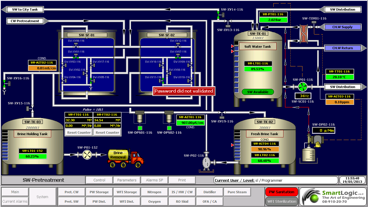
מושג עיקרי בבקרה אוטומטית הוא מערכת בקרה אוטומטית, שמספקת בקרה וניטור של סוגים שונים של מערכות רלוונטיות, כגון ייצור, ניהול, וכו'. לדוגמה, אפשר לתכנן מערכת בקרה לשימור גבולות מוגדרים של ערכי טמפרטורה, לחץ ולחות בתוך מתקן ייצור.

מערכת בקרה מורכבת ממגוון רכיבים מבוקרים, ומשוב (feedback) של נתוני בקרה ממכשירי מדידה במעגל סגור (closed loop), שמאפשרים פעולה נכונה של רכיבי המערכת (כגון אלו הרשומים בהמשך) בהתאם לערכים שנקבעו מראש:

  • רגשים (sensors), שמודדים תנאים פיסיקליים, כגון טמפרטורה, לחץ, גובה נוזל, וכו'.
  • בקרים (controllers), שיכולים להיות החל מרכיבים פיסיקליים פשוטים ועד בקרים דיגיטליים מורכבים או מחשבים משובצים (embedded).
  • מפעילים (actuators), שמגיבים למדידות הרגשים ופועלים בהתאם להוראות הבקרים; לדוגמה, בבקרת כניסת אנרגיה, כגון, זרימת גז למבער במערכת חימום, או חשמל למנוע במקרר, או משאבה.
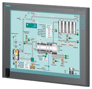
  • תחנת/ות מחשב, שמקושרות לבקרים. המחשבים משמשים להצגת ערכים נמדדים שהתקבלו מהבקרים במסכים של ממשק אדם/מכונה (HMI – Human/Machine Interface), ולשנות ערכים נקבעים (settings), כדי לאפשר ניטור ובקרה עכשוויים (online) של המערכת ע"י המשתמשים.

 רגשים (Sensors)

רגשים, שמודדים תנאים פיסיקליים, כוללים בד"כ אמצעים לשדר את הערכים שהם מודדים ל בקרים המתאימים; במקרה זה הם גם נקראים משדרים (transmitters). הם יכולים לכלול בנוסף מצגות ערכים (indicators) לפיקוח ויזואלי קל ע"י המשתמש.
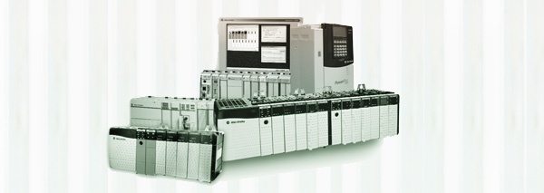
בקרים (Controllers)

הבקרים הם הרכיבים החשובים ביותר במערכת בקרה אוטומטית. הם יכולים להיות החל מרכיבים פיסיקליים פשוטים ועד בקרים דיגיטליים מורכבים או מחשבים משובצים. הבקרים מנתחים ומעבדים את הערכים הנמדדים ע"י הרגשים ושולטים על המערכת בהתאם, בצירוף עם מחשבים מחוברים לבקרים; המחשבים כוללים תוכנות HMI לניטור ובקרה של המערכת.

דוגמאות של בקרים:

  •  בקרים לוגיים שניתנים לתכנות (PLCs – Programmable Logic Controllers)*
  • בקרים דיגיטליים ישירים (DDCs – Direct Digital Controllers)
  • יחידות קצה רחוקות (RTUs – Remote Terminal Units)

מפעילים (Actuators)

המפעילים מגיבים למדידות הרגשים ופועלים בהתאם להוראות הבקרים. דוגמאות של המפעילים הם: מתגים המגיבים להפרשי לחץ (DPSs – Differential Pressure Switches), מרסני נפח ממונעים (MVDs – Motorized Volume Dampers), מקררים ותנורים חשמליים, וכן משאבות ומפוחים, שמאפשרים כיוונוני טמפרטורה, לחץ, לחות, ותנאים פיסיקליים אחרים, כדי לתחום אותם בהתאם לערכים שנקבעו מראש.

תחנת/ות מחשב

תחנה מחשב אחת או יותר שמקושרות לבקרים מקבלות ערכים נמדדים מהבקרים ומציגים ערכים אלו, וכמו כן מצב פעולת רכיבי המערכת במסכים של ממשק  HMI לניטור עכשווי של המערכת. הערכים הנמדדים ניתנים להשוואה עם ערכים מותרים שנקבעו מראש, ואם הערכים הנמדדים חורגים מהגבולות המותרים, אפשר להציג הודעת אזהרה. ניתן להשתמש בממשק  HMI גם כדי לשנות את הערכים המותרים ולנטר את מצב פעולת רכיבי המערכת כתגובה לשינויים.

* סמארט לוג'יק משתמשת בבניית מערכות אוטומציה ובקרה בבקרים של חברת Siemens  וחברת אלן ברדלי – Allen-Bradley.

סמארטלוג'יק משווקת בין היתר את המוצרים הנ"ל:

6XV1830-0EH10, 6ES7131-4BF00-0AA0, 6ES7193-4CA40-0AA0, 6ES7134-4GD00-0AB0, 6ES7193-4CA40-0AA0, 6ES7138-4CA01-0AA0, 6ES7193-4CC20-0AA0, 6ES7590-1AB60-0AA0, 6ES7511-1AK00-0AB0, 6ES7954-8LP01-0AA0, 6ES7155-6AU00-0BN0, 1746-NO4V, 1769-L16ER-BB1B.


ממשק אדם-מכונה HMI – אוטומציה ובקרה

מה זה HMI?

ממשק אדם-מכונה Human-Machine Interface – HMI מתרחש בתחום בו חלה אינטראקציה בן בני אדם ומכונות. מטרת האינטראקציה היא אפשרות  לניטור ובקרה יעילים של  אותן מכונות ע"י מפעיליהן, כאשר המכונות מספקות מידע בהיזון חוזר שמאפשר למפעילים לקחת החלטות נכונות בזמן התהליך. לממשק זה יש שימוש נרחב בעיצוב, יצור ובקרה על ציוד תעשייתי, ועל ניטור ובקרה על תהליכים תעשייתיים.

עם השימוש הגדל במחשבים אישיים ובקרים ממוחשביםProgrammable Logic Controller – PLC, הפך HMI למונח  המתייחס לרוב לייצוג הגרפי של הציוד והתהליכים התעשייתיים על פני מסכי המחשבים.

סמארטלוג'יק משתמשת ב -PLCs מתוצרת סימנס (Siemens) ואלן ברדלי (Allen Bradley)  לדוגמא :

6XV1830-0EH10, 6ES7131-4BF00-0AA0,6ES7193-4CA40-0AA0,6ES7134-4GD00-0AB0,6ES7193-4CA40-0AA0, 6ES7138-4CA01-0AA0,6ES7193-4CC20-0AA0, 6ES7590-1AB60-0AA0, 6ES7511-1AK00-0AB0, 6ES7954-8LP01-0AA0,6ES7155-6AU00-0BN0

מונח אחר, פחות שימושי הוא ממשק איש-מכונה הוא  Man-Machine Interface – HMI. מונח זה היה נפוץ אך זכה להתרעמות מצד ארגוני הנשים שדיברו על כך שגם נשים הם משתמשות בממשקים אלו ומהוות חלק מהם כך שונה השם למונח הכללי אדם או באנגלית Human.

HMI מערב ציוד (חומרה) היקפי, ורכיבי תוכנה, כגון ממשקים גרפיים.

בתחום המקושר ל- HMI, שנקרא Human-Computer Interaction – HCI, חוקרים את הייצוב והשימוש בטכנולוגיית המחשב, תוך מיקוד מיוחד בממשקים בין אנשים ומחשבים. החוקרים בתחום זה מתבוננים בצורות שבהם אנשים פועלים מול מחשבים, ומעצבים טכנולוגיות  שמאפשרות אינטראקציה  בין אנשים ומחשבים באופנים חדשים.

אנשים  פועלים מול מחשבים בצורות שונות, והממשק בו משתמשים משחק תפקיד מכריע בהקלה באינטראקציה. אפליקציות במחשב שולחני, דפדפן (browser) אינטרנטי,  מחשבים נישאים, וכו', משתמשות בממשק לשימוש גרפי Graphical User Interface – GUI באופן הנפוץ ביותר; ממשק לשימוש קולי Voice User Interface – VUI, פחות נפוץ, משמש לזיהוי דיבור ומערכות סינתוז synthesizing. השימוש ב- multi-modal GUI מאפשר להשתלב עם גורמים מסוימים שלא ניתנים  לתקשורת עם כלי ממשק אחרים.

שימוש ב-HMI לצורכי בקרה ואוטומציה

בתחום הבקרה והאוטומציה אנו עוסקים רבות בממשק Human-Machine Interface – HMI בעת תכנון ותפעול מערכות בקרה תעשייתיות.

תכנון וביצוע פרויקטים הנדסיים בתחום הבקרה האוטומציה היא המומחיות של סמארטלוג'יק, בקרה מפעלית ובקרות תהליך, בקרות מבנה BMS.  שיטות עבודה שלנו מאפשרות ביצוע אינטגרציה במהירות שיא, בין פרויקט חדש ומערכות המפעל הקיימות. סמארטלוג'יק מבצעת פרויקטי אוטומציה ובקרה מודולארית למתקני יצור תוך שימוש בתקן S-88.  סמארטלוג'יק היא גם  נציגה בלעדית של Siemens בארץ לתמיכה במערכת PCS7 ועובדת על בסיס קבוע, עם מרכז התמיכה העולמי בגרמניה באמצעות מערכת בקרת איכות מחמירה העומדת בתקן ISO9000.

להדרכה איך גורמים ל HMI לעבוד עם הרשאות ווינדוס לחצו כאן.

אוטומציה ובקרה – Create the Generic PLC Model

אוטומציה ובקרה –  Create the Generic PLC Model

PLC is a digital computer used for automation of elector mechanical processes, such as control of machinery on factory assembly lines.

PLCs are usually programmed using application software (SW) on personal computers (PCs). The PC is connected to the PLC through Ethernet, RS-232, RS-485 or RS-422 cabling. Most PLCs used by smartlogic when designing an automation and control systems are the Siemens PLCs and Allen Bradley‘s.The programming SW allows entry and editing of the ladder-style logic. Generally the SW provides functions for debugging and troubleshooting the PLC software, for example, by highlighting portions of the logic to show current status during operation or via simulation. The SW will upload and download the PLC program, for backup and restoration purposes.

:This is how to create the generic PLC model

Important: Each device included in the project that will be using the alternate configuration must have a STAT_PLC model. If the STAT_PLC model is not selectable from the device configuration screen, it can be added to the CIMPLICITY configuration by editing the IC646TME000.MODEL configuration file located in the BSM_DATA subdirectory of the original CIMPLICITY distribution.

Add the following line to the file using a text editor.

MB_TCPIP|STAT_PLC|35

For existing projects

Important: It is strongly recommended that entries in the .ini file be restricted to devices with a model type of STAT_PLC or Generic PLC.

Refer to the product documentation for instructions for creating the STAT_PLC model.

Create the Generic PLC model to use in a project using the Modbus Ethernet protocol

Click Tools>Command Prompt on the Workbench menu bar.

Type cd master in the Command Prompt window and press Enter.

Type idtpop model and press Enter.

Type notepad model.idt and press Enter.

Add the following lines:

MB_TCPIP|Generic PLC|180

MB_TCPIP|STAT_PLC|35

Save model.idt and close the text editor

Type scpop model at the command prompt and press Enter

Close the Command Prompt window

Perform a configuration update in the project's Workbench

Note: The STAT_PLC model sizing is different from the Generic PLC model if you do one of the following

Define the parameter Use These Domain Sizes to be 0

Do not specify all of the domains.

Here are some examples of the PLCs used by smartlogic: 6XV1830-0EH10, 6ES7131-4BF00-0AA0,6ES7193-4CA40-0AA0,6ES7134-4GD00-0AB0,6ES7193-4CA40-0AA0, 6ES7138-4CA01-0AA0,6ES7193-4CC20-0AA0, 6ES7590-1AB60-0AA0, 6ES7511-1AK00-0AB0, 6ES7954-8LP01-0AA0,6ES7155-6AU00-0BN0

ולידציה – FRS for Compliance with 21 CFR Part 11

Functional Requirements Specification -FRS Regarding Requirements for Compliance with 21 CFR Part 11

This FRS presents SmarLogic's functional requirements in response to the User Requirements Specification (URS) . These functional requirements should be met in order to ensure  Control and Monitoring System complies with 21 CFR Part 11.

This FRS must be considered for the system design, build, installation, operation and testing requirements, and for traceability purposes along the product life cycle up to the Operational Qualification (OQ) stage.

                              Responsibility

The Validation Engineer is responsible for writing this protocol. The Control, Automation & Validation Engineer is responsible for ensuring the preparation and approval of this protocol.

The Control Engineer, Division Process Engineer and QA Manager are responsible of approving this document before development and on-site implementations.

The following sections list the functional requirements determined by the relevant groups of the system upgrading. Each functional requirement number is followed by the corresponding user requirement paragraph number for design qualification purpose

                            Glossary

ER – Electronic Record

DB – Database

FRS – functional requirements Specification

HMI – Human/Machine Interface

HSP – High Set-Point

HW – Hardware

IQ –  Installation Qualification

LSP –  Low Set-Point

OQ – Operational Qualification

OS – Operating System

PLC ָָ*- Programmable Logic Controller

QA – Quality Assurance

SCR – Screen

SOP – Standard Operating Procedures

SP – Set-Point

SSO – Schedule of System Operation

SW – Software

TP – Test Point

URS – User Requirements Specification

Requirements for Meeting 21 CFR Part 11

                        Top-Level Requirements

This section covers the proposed solutions for meeting 21 CFR Part 11 presented in the URS for a new WinCC HMI System. This system must allow the :following five main functionalities

Ensure the system integrity

Control the access to the system by logical security

Audit events that create and modify electronic records

Apply electronic signatures to the system

Backup and archive data to ensure record integrity in case of failure

                      Detailed Requirements

This section describes SmartLogic's solutions that will meet the detailed requirements listed in the URS. These requirements are divided into 6 categories for the sake of clarity:

Electronic Records

Security

Audit Trail

Archive

Backup

* Here are some examples of the PLCs used by smartlogic: 6XV1830-0EH10, 6ES7131-4BF00-0AA0,6ES7193-4CA40-0AA0,6ES7134-4GD00-0AB0,6ES7193-4CA40-0AA0, 6ES7138-4CA01-0AA0,6ES7193-4CC20-0AA0, 6ES7590-1AB60-0AA0, 6ES7511-1AK00-0AB0, 6ES7954-8LP01-0AA0,6ES7155-6AU00-0BN0

ולידציה – Operation Qualification – OQ- part 1

ולידציה – Operation Qualification – OQ- part 1

Protocol Preparation Overview

The Operation Qualification (OQ) protocol is part of the validation documentation that covers the verification of the proper operation of the system under validation in the user's facility. This OQ protocol is generic, and the system may include a PC with Human/Machine Interface (HMI), a Programmable Logic Controller* (PLC), pressure, temperature and humidity transmitters, and other monitoring and control components designed to maintain the user's facility in proper environmental conditions (temperature, pressure and humidity)

This OQ protocol is intended to verify that the system under validation operates according to the acceptance criteria specified in the Schedule of System Operation (SSO), and also meets the vendor's requirements and the user's specifications. It must be reviewed and approved prior to the OQ performance

OQ Protocol Contents

The OQ protocol is structured in a relatively standard fashion, with predetermined chapters and sections, where the final contents are tailored according to the type and size of the system under validation

:The chapters and sections of an OQ protocol are

Documents Verification – procedure intended to verify that all the documents required for performing the OQ procedure are approved and available

OQ Test Procedures – this is the main part of the protocol, and provides the description of the test procedures and the result tables for filling and approving the test results

: Note

As the final contents of the OQ protocol are tailored according to the type and size of the system under validation, and this document is generic, it covers test procedures that may not be necessary in small or simple systems

Documents Verification

:This procedure is intended to verify that all the documents required for performing the OQ procedure are approved and available. These documents are

Functional Requirements Specification (FRS)

Installation Qualification (IQ) Protocol

Piping and Instrumentation Drawing – P&ID

Input/Output (I/O) List

Schedule of System Operation (SSO)

OQ Test Procedures

This chapter contains all the test procedures or verification required to verify the system under validation is properly installed and can be properly operated according to the supplier's requirements and user's specifications

:Each test procedure or verification must include the same contents

Purpose or Objective

Procedure or Method

Acceptance Criteria

Test Results

*Here are some examples of the PLCs used by smartlogic: 6XV1830-0EH10, 6ES7131-4BF00-0AA0,6ES7193-4CA40-0AA0,6ES7134-4GD00-0AB0,6ES7193-4CA40-0AA0, 6ES7138-4CA01-0AA0,6ES7193-4CC20-0AA0, 6ES7590-1AB60-0AA0, 6ES7511-1AK00-0AB0, 6ES7954-8LP01-0AA0,6ES7155-6AU00-0BN0

אוטומציה ובקרה – חיבור הציוד לתקשורת SATEC

אוטומציה ובקרה – חיבור הציוד לתקשורת SATEC

 במאמר הבא נסקור את הייחודיות של מד ההספק של SATEC וכיצד ניתן להתחבר באמצעותו לרשתות תקשורת

כל דגמי Powermeter (מד הספק) של  SATEC העכשוויים מצוידים באחד או שני פורטים לתקשורת סריאלית המבודדים באופן אופטי. על כן הם מאפשרים פעילות בסוגים שונים של רשתות תקשורת, כולל אלו עם הפרעות של מתח גבוה ושדות מגנטיים.

פורט תקשורת תומך בממשקים סטנדרטיים מסוג   RS-232 eia, RS-422 או RS-485 (לפי בחירת המשתמש או היצרן), שמאפשר חיבור למחשב,PLC* – Programmable Logic Controller או מודם.

התקשורת פועלת במתכונת אדון-עבד (Master-Slave), כאשר המחשב המארח (host) פועל כאדון והמכשיר הנשלט פועל כעבד, ז"א, המחשב משדר בקשות למכשיר שמגיב למחשב; אבל המכשיר לא משדר מידע למחשב ביוזמתו. המחשב המארח סוקר את המכשיר כדי לקבל נתוני מדידה, או כדי לקרוא או לתכנת את הפרמטרים בקונפיגורציה של ה- Powermeter.

חיבורים מסוג multi-drop

מכשירי SATEC ניתנים לשימוש ברשתות מסוג multi-drop. המכשירים מקושרים לרשת דרך פורטים לתקשורת מסוג RS-422 או RS-485. שני פורטים אלו הם סטנדרטיים לממשקים דיפרנציאלים סריאליים (serial differential interface standards). מכיוון שמשתמשים במד דיפרנציאלי, הרעש ברשת כמעט מושתק.

בסטנדרט RS-422, המכשירים מקושרים לרשת דרך שני זוגות חוטי חשמל, זוג אחד לצורך שידור והשני לקליטה (full duplex).

בסטנדרט RS-485, המכשירים מקושרים לרשת דרך זוג אחד של חוטי חשמל, כאשר הזוג הבודד משמש שידור וגם לקליטה (half duplex), ז"א, המשדר והמקלט של המכשיר מחוברים במקביל (in parallel).

הרשת מחוברת לפורט קישור (מסוג RS-422 או RS-485) של מחשב (או PLC) שמשמש כמארח מקומי (local host), או לפורט קישור מחשבי מסוג RS-232 דרך ממיר . RS-232של SATEC. ממיר זה תומך בעד 32 מכשירים ומספק גילוי נתונים אוטומטי automatic data detection)), ללא צורך ב-RTS  חיצוני. המרחק בין הממיר והמכשיר RS-232 יכול להגיע עד 15 מטר. ניתן לחבר מחשב שמשמש כמארח מקומי לרשת דרך ממיר RSC-232 ושני מודמים. הממיר והמודם הראשון מותקנים ביחד עם המכשירים, והמודם השני עם המחשב.

חיבורי תקשורת

ניתן לחבר עד 32 מכשירים לרשת תקשורת מסוגmulti-drop  RS-422/RS-485, שמורכבת מזוג כבלים עם זוגות חוטי חשמל מפותלים ומוגנים (עבור RS-485: 2 זוגות, אחד פעיל ואחד רזרבי; עבור RS-422: 3 זוגות, 2 פעילים ואחד רזרבי). האורך הכולל של הכבל יכול להגיע עד 1200 מטר.

הכבל מורכב מקטעים בין המכשירים. ציפוי ההגנה (shield) של כל קטע כבל מסוג RS-422/RS-485 חייב להיות מחובר לאדמה באחד מקצותיו בלבד. וודא שהפולריות נכונה כאשר אתה מחבר את הטרמינלים (+) ו- ( ) של כל פורט מסוג RS-422/RS-485.

חוטי החשמל בשימוש חייבים להיות בגדלים ביןAWG  22 ו- AWG 12 (mm2 3.30.3-).

מומלץ להשתמש ברצועת טרמינל בכל חיבור של מכשיר לרשת, כדי לאפשר פירוק קל של מכשיר במידת הצורך.

קונפיגורציות של חיווט

רשת מסוג  multi-dropחייבת קונפיגורציה של נקודה-לנקודה (point-to-point configuration), ז"א, הטרמינלים (+) ו- ( -) של כל מכשיר חייבים להיות מחוברים לטרמינלים המתאימים של המכשיר הבא. מומלץ להשתמש בשיטת חיווט בקו ישר. חייבים להימנע מכל חיבור עם ענף בקו העיקריmain bus) ), כגון שיטות כוכב (star) ו-T  (tee); במקרים אלו יווצרו השתקפויות (reflections) של אותות שעלולות לגרום להתאבכות (interference) ראה איורים 1-4 (1-4Figures ).

כל נקודה סופית בקו העיקריmain bus) ) חייבת להסתיים עם נגד של1/4  ווט (Watt). נגדים אלו מצמצמים את השתקפויות Aעלולים לשבש את אותות הנתונים על הקו. נגדים אלו מחוברים בין הטרמינלים (+) ו- (- ) של המכשירים בכל קצה של הקו העיקרי. (כאשר משתמשים בממיר RSC-232 בחיבור למחשב, הנגד לא ישים מכיוון שהוא כבר מחובר בתוך הממיר). ערך הנגד חייב להתאים לאימפדנס הקווי (line impedance) של הכבל בשימוש, הערך האופייני נע בין 200 ו- 500 אוהם (Ohm).

רשתות תקשורת מסוג single-drop

מכשיר אחד יכול להתחבר למחשב מארח (computer host) אחד או לפורט קישור של מודם RS-232.

החיבור מחייב כבל עם זוגות חוטי חשמל מפותלים ומוגנים (3 זוגות: אחד פעיל, אחד מחודר לאדמה ואחד רזרבי). אורך יכול להגיע עד 15 מטר ניתן להאריך את המרחק הזה תוך שימוש בקצב שידור baud נמוך יותר, כבלים עם ציפוי ההגנה (shielded) או משחזר (repeater).

חוטי החשמל בשימוש חייבים להיות בגודלAWG  24 (mm2 0.5).

פרוטוקולים של תקשורת

כל מכשירי SATEC תומכים לפחות בשני פרוטוקולים: ASCII ו- Modicon Modbus RTU. שניהם פרוטוקולים פתוחים שניתנים לשימוש ע"י תוכנה של מארח ששייך לגוף שלישי  (third-party host-based software) נגישים לכל הנתונים ורגיסטרים של קונפיגורציה (registers configuration) של Powermeter.

מכשירים רבים של SATEC תומכים גם בפרוטוקול DNP3.0.

*סמארט לוג’יק משתמשת בבניית מערכות אוטומציה ובקרה בבקרים של חברת Siemens  וחברת אלן ברדלי – Allen-Bradley

דוגמאות ל- PLCs  בשימוש סמארטלוג’יק:

6XV1830-0EH10, 6ES7131-4BF00-0AA0, 6ES7193-4CA40-0AA0, 6ES7134-4GD00-0AB0, 6ES7193-4CA40-0AA0, 6ES7138-4CA01-0AA0, 6ES7193-4CC20-0AA0, 6ES7590-1AB60-0AA0, 6ES7511-1AK00-0AB0, 6ES7954-8LP01-0AA0, 6ES7155-6AU00-0BN0, 1746-NO4V, 1769-L16ER-BB1B


אוטומציה ובקרה – העלאת תוכנה מבקר סימנס

אוטומציה ובקרה – PLCs Topic – Part 2

 אוטומציה ובקרה – PLCs Topic – Part 2

This articular is the third part of our  review about PLCs. After PLCs Functionality&Features and PLCs Topic – part 1 that covers the subjects of  Scan Time, System Scale, User interface & Communications, this part is about PLCs Programming, Digital and Analog Signals & PLC Advantages.

PLC– Programming

PLC programs are typically written in a special application on a PC, then downloaded by a direct-connection cable or over a network to the PLC. The program is stored in the PLC either in battery-backed-up RAM or some other non-volatile flash memory.

IEC 61131-3 defines several programming languages for programmable control systems, which emphasize logical organization of operations.

While the fundamental concepts of PLC programming are common to all manufacturers, differences in I/O addressing, memory organization and instruction sets mean that PLC programs are never perfectly interchangeable between different makers. Even within the same product line of a single manufacturer, different models may not be directly compatible.

PLC – Digital and Analog Signals

Digital or discrete signals behave as binary switches, yielding simply an On or Off signal (1 or 0, True or False, respectively). Push buttons, limit switches, and photoelectric sensors are examples of devices providing a discrete signal. Discrete signals are sent using either voltage or current, where a specific range is designated as On and another as Off. For example, a PLC might use 24 V DC I/O, with values above 22 V DC representing On, values below 2VDC representing Off, and intermediate values undefined. Analog signals are like volume controls, with a range of values between zero and full-scale. These are typically interpreted as integer values (counts) by the PLC, with various ranges of accuracy depending on the device and the number of bits available to store the data. Pressure, temperature, flow, and weight are often represented by analog signals. Analog signals can use voltage or with a magnitude proportional to the value of the process signal. Current inputs are less sensitive to electrical noise (i.e. from welders or electric motor starts) than voltage inputs.

PLC Advantages Relative to Other Control Systems

PLCs are well adapted to a range of automation tasks. These are typically industrial processes in manufacturing where the cost of developing and maintaining the automation system is high relative to the total cost of the automation, and where changes to the system would be expected during its operational life. PLCs contain input and output devices compatible with industrial pilot devices and controls; little electrical design is required, and the design problem centers on expressing the desired sequence of operations. PLC applications are typically highly customized systems, so the cost of a packaged PLC is low compared to the cost of a specific custom-built controller design.

Here are some examples of the PLCs used by smartlogic: 6XV1830-0EH10, 6ES7131-4BF00-0AA0,6ES7193-4CA40-0AA0,6ES7134-4GD00-0AB0,6ES7193-4CA40-0AA0, 6ES7138-4CA01-0AA0,6ES7193-4CC20-0AA0, 6ES7590-1AB60-0AA0, 6ES7511-1AK00-0AB0, 6ES7954-8LP01-0AA0,6ES7155-6AU00-0BN0

אוטומציה ובקרה – PLC Topics – Part 1

אוטומציה ובקרה – PLC Topics – Part 1

 PLC – Scan Time

A PLC program is generally executed repeatedly as long as the controlled system is running. The status of physical input points is copied to an area of memory accessible to the processor, sometimes called the "I/O Image Table". The program is then run from its first instruction rung down to the last rung. It takes some time for the processor of the PLC to evaluate all the rungs and update the I/O image table with the status of outputs. This scan time may be a few milliseconds for a small program or on a fast PLC.

PLC – System Scale

A small PLC has a fixed number of connections built in for inputs and outputs. Typically, expansions are available if the base model has insufficient I/O.

Modular PLCs have a chassis (also called a rack) into which are placed modules with different functions. The processor and selection of I/O modules are customized for the particular application. Several racks can be administered by a single processor, and may have thousands of inputs and outputs. A special high speed serial I/O link is used so that racks can be distributed away from the processor, reducing the wiring costs for large plants.

PLC- User interface

PLCs may need to interact with people for the purpose of configuration, alarm reporting or everyday control. Human-machine interface (HMI) is employed for this purpose. HMIs are also referred to as man-machine interfaces (MMIs) and graphical user interface (GUIs). A simple system may use buttons and lights to interact with the user. Text displays are available as well as graphical touch screens. More complex systems use programming and monitoring SW installed on a computer, with the PLC connected via a communication interface.

PLC- Communications

PLCs have built-in communications ports and corresponding communications protocols, such as RS-232, EIA-485, Ethernet, Modbus, BACnet or DF1.

Most PLCs can communicate over a network to some other system, such as a computer running a SCADA (Supervisory Control And Data Acquisition) system or web browser.

PLCs used in larger I/O systems may have peer-to-peer (P2P) communication between processors. This allows separate parts of a complex process to have individual control while allowing the subsystems to co-ordinate over the communication link.

Here are some examples of the PLCs used by smartlogic: 6XV1830-0EH10, 6ES7131-4BF00-0AA0,6ES7193-4CA40-0AA0,6ES7134-4GD00-0AB0,6ES7193-4CA40-0AA0, 6ES7138-4CA01-0AA0,6ES7193-4CC20-0AA0, 6ES7590-1AB60-0AA0, 6ES7511-1AK00-0AB0, 6ES7954-8LP01-0AA0,6ES7155-6AU00-0BN0

אוטומציה ובקרה – PLC – Programmable Logic Controller

אוטומציה ובקרה – PLC – Programmable Logic Controller

A Programmable Logic Controller – PLC is a digital computer used for automation of electromechanical processes, such as control of machinery on factory assembly lines. Unlike general-purpose computers, the PLC is designed for multiple inputs and output arrangements, extended temperature ranges, immunity to electrical noise, and resistance to vibration and impact. Programs to control machine operation are typically stored in battery-backed-up or non-volatile memory. A PLC is an example of a hard real time system since output results must be produced in response to input conditions within a limited time, otherwise unintended operation will result.

PLCs are usually programmed using application software (SW) on personal computers (PCs). The PC is connected to the PLC through Ethernet, RS-232, RS-485 or RS-422 cabling. Most PLCs used by smartlogic when designing an automation and control systems are the Siemens PLC and Allen Bradley's.The programming SW allows entry and editing of the ladder-style logic. Generally the SW provides functions for debugging and troubleshooting the PLC software, for example, by highlighting portions of the logic to show current status during operation or via simulation. The SW will upload and download the PLC program, for backup and restoration purposes.

PLC Functionality

The functionality of the PLC includes sequential relay control, motion control, process control, distributed control systems and networking. The data handling, storage, processing power and communication capabilities of some modern PLCs are approximately equivalent to desktop computers.

PLC Features

The PLC unit consists of separate elements, such as power supply, controller, relay units for in- and output

The main difference from other computers is that PLCs are armored for severe conditions (such as dust, moisture, heat, cold) and have the facility for extensive input/output (I/O) arrangements. These connect the PLC to sensors and actuators. PLCs read limit switches, analog process variables (such as temperature and pressure), and the positions of complex positioning systems. On the actuator side, PLCs operate electric motors, pneumatic or hydraulic cylinders, magnetic relays, solenoids, or analog outputs. The input/output arrangements may be built into a simple PLC, or the PLC may have external I/O modules attached to a computer network that plugs into the PLC.

 Here are some examples of the PLCs used by Smartlogic: 6XV1830-0EH10, 6ES7131-4BF00-0AA0, 6ES7193-4CA40-0AA0, 6ES7134-4GD00-0AB0, 6ES7193-4CA40-0AA0, 6ES7138-4CA01-0AA0, 6ES7193-4CC20-0AA0, 6ES7590-1AB60-0AA0, 6ES7511-1AK00-0AB0, 6ES7954-8LP01-0AA0, 6ES7155-6AU00-0BN0, 1746-NO4V, 1769-L16ER-BB1B