Smartlogic

אוטומציה ובקרה – בקר דיגיטלי ישיר DDC

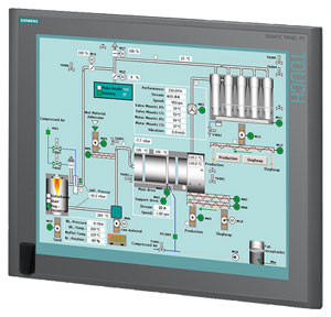
אוטומציה ובקרה – בקר דיגיטלי ישיר Direct Digital Controller -DDC

המונח DDC  מייצג בד"כ בקרה דיגיטלית ישירה (Direct Digital Control) אך גם בקר דיגיטלי ישיר (Direct Digital Controller).

בקרה מסוג DDC היא בקרה אוטומטית של מצב או תהליך ע"י בקר דיגיטלי. בקר מסוג DDC מורכב מבקרים מבוססים על מיקרופרוססורים (microprocessors) עם בקרה לוגית מבוצעת בעזרת תוכנה. מתמרים אנלוגיים/דיגיטליים (analog-to-digital (A/D) converters) מתמירים ערכים אנלוגיים לאותות דיגיטליות שמיקרופרוססור יכול להשתמש בהן. רגשים אנלוגיים יכולים להפיק ערכי התנגדות, מתח או זרם. רוב מערכות הבקרה מבזרים את התוכנה בין בקרים מרוחקים (remote) כדי להימנע מהצורך ביכולת בתקשורת רציפה ולאפשר יכולת פעולה עצמאית (stand-alone) של הבקרים. מחשב המערכת משמש בעיקר לניטור המצב של מערכת ניהול האנרגיה, שימור עותקי תוכניות לגיבוי, ולרישום התראות ואירועים.

יתרונות ה- DDC – בקר דיגיטלי ישיר

יתרונות בקרת DDC מעל לטכנולוגיות בקרה קודמות (פניאומאטיקה או בקרה אלקטרונית מבוזרת) מתבטאות בשיפור יעילות הבקרה במערכת. שלושת יתרונות העיקריים של בקרת DDC הם:

  • שיפור ביעילות הבקרה
  • שיפור ביעילות תפעול המערכת
  • שיפור ביעילות השימוש באנרגיה

 שיפור ביעילות הבקרה

DDC מעניקה בקרה יעילה יותר של מערכות חימום, אוורור ומיזוג אוויר (HVAC – Heating, Ventilating and Air Conditioning), ע"י הפקת נתונים מנוטרים מדויקים יותר. הרגשים האלקטרוניים שמודדים את הפרמטרים הנפוצים במערכות HVAC  (טמפרטורה,לחות ולחץ) הם מטבעם מדויקים בהרבה מקודמיהם הפניאומאטיים. מכיוון שלוגיקת חוג הבקרה כלול בתוכנת ה- DDC, ניתן לשנות את הלוגיקה הזו בקלות. כך, ה- DDC מעניק גמיש רבה יותר בשינוי לו"ז לאיפוס (reset), נקודות נקבעות (set points) ולוגיקת בקרה מערכתית.

שיפור ביעילות תפעול המערכת

מערכות DDC מטבעם יכולות להשתלב בקלות רבה בתוך מערכות מבוססות על מחשב, כגון מערכות בקרת אש, כניסה/אבטחה (access/security), תאורה, ניהול תחזוקה, ועוד. יכולות המגמות ב- DDC מאפשרות לטכנאי או מהנדס לאתר תקלות ולפתור אותן. יכולות אלו מאפשרות גם להציג את הנתונים בפורמטים שונים. הנתונים מאפשרים קריאה של המגמות שיכולות להישמר ולעבור ניתוח לגילוי מגמות של ביצועי המערכות לאורך נתון.

שיפור ביעילות השימוש באנרגיה

קיימות אסטרטגיות בקרה רבות להשגת יעילות בשימוש באנרגיה בלוגיקה פניאומטית שניתנות לשכפול בלוגיקת DDC. האפשרות להוסיף פונקציות מתמטיות מורכבות יותר (שמושגות בקלות בתוכנה), מובילה לשגרות(routines)  נוספות יעילות מבחינה אנרגטית שניתנות לשימוש עם DDC.

אסטרטגיות כגון ניטור והגבלת צריכת אנרגיה ניתנות להשגה בקלות עם מערכות DDC. אפשר לנטר ולבקר צריכה כוללת במתקן יצור ע"י איפוס נקודות נקבעות (set points) מבוססות על רמות צריכה שונות.

דפוסי צריכת אנרגיה ניתנות לניטור ע"י אחסנת מגמות. אפשר גם לקבוע לו"ז של הפעלת/כיבוי (on/off) ציוד באפליקציות בהן הלו"ז משתנה בתכיפות.

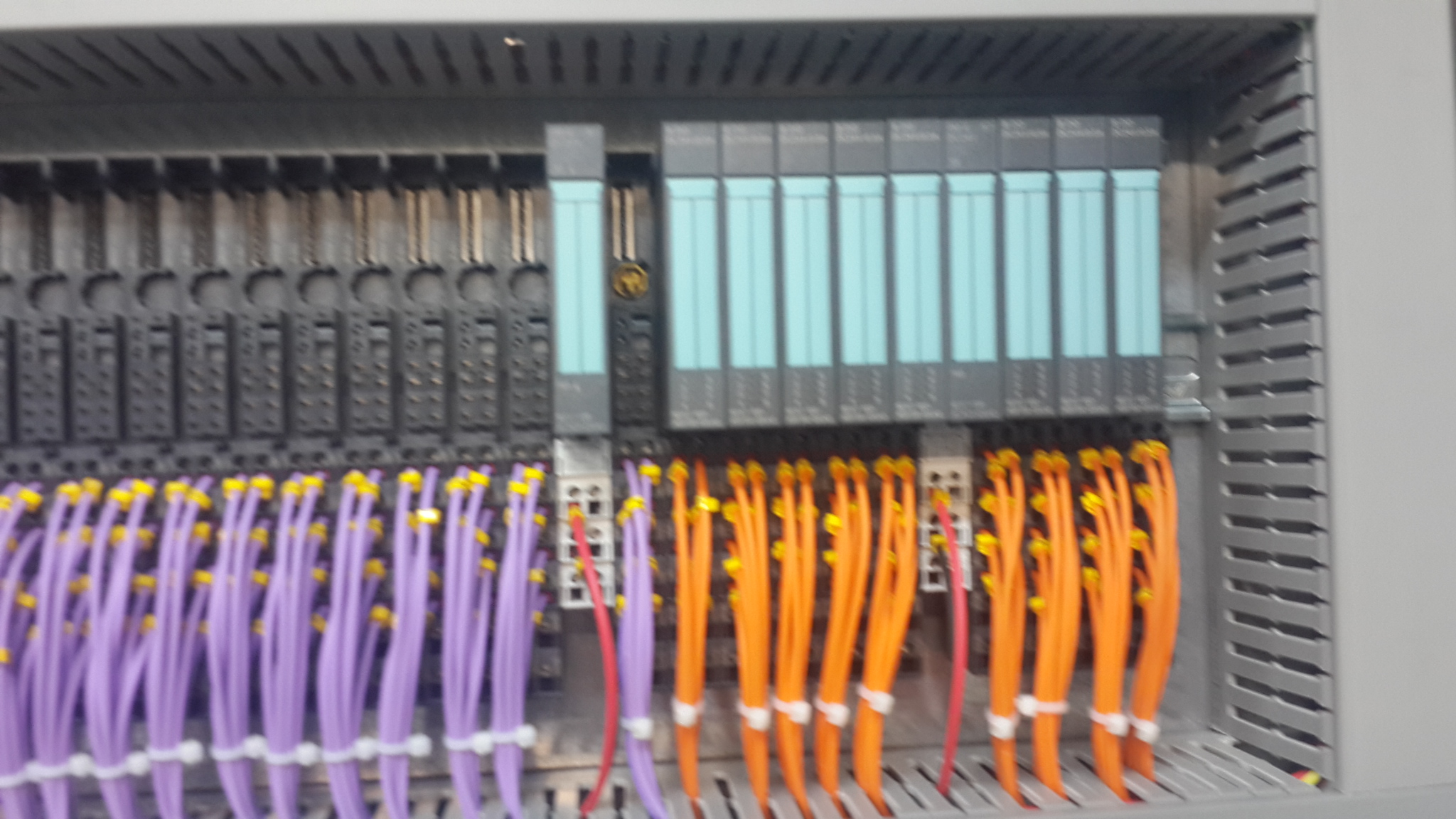
 רכיבי בקר דיגיטלי ישיר DDC

נקודות (Points)

המונח נקודה (Point) משמש לתיאור מיקום אחסנת נתונים במערכת DDC. הנתונים יכולים להגיע מרגשים או מלוגיקה או חישובי תוכנה. למיקום כל נתון מאוחסן יש אמצעי ייחודי לזיהוי או מיעון.

נתונים (Data)

נתוני DDC ניתנים לסיווג בשלושה אופנים:

  • לפי סוג (type)
  • לפי כיוון זרימה (flow direction)
  • לפי מקור (source)

נתונים לפי סוג (Data Type)

לפי סיווג זה, נתונים יכולים להיות דיגיטליים, אנלוגיים ומצטברים.

נתונים דיגיטליים נקראים גם דיסקרטיים או בינאריים. ערך של נתון דיגיטלי יכול להיות 0 או 1, ומייצג בד"כ מצב או סטאטוס של קבוצת מגעים.

נתונים אנלוגיים הם מספריים, דצימאליים, ובד"כ מציגים ערכי כניסה כגון טמפרטורה,לחות יחסית ולחץ, או משתנה אחר הנמדד במערכת חימום, אוורור ומיזוג אוויר (HVAC – Heating, Ventilating and Air Conditioning).

נתונים מצטברים הם גם מספריים, דצימאליים, אך כאן סיכום הערכים מאוחסן.

נתונים לפי כיוון זרימה (Data Flow Direction)

נתונים אלו מתייחסים לכיוון הזרימה ביחס לרכיב/לוגיקת DDC: נקודות כניסה מציגות נתונים המשמשים כמידע נכנס ל- DDC, ונקודות יציאה מציגות מידע יוצא מה- DDC.

נתונים לפי מקור (Data Source)

נתונים ניתנים לסיווג כחיצוניים אם הם מתקבלים מרכיב חיצוני או נשלחים לרכיב חיצוני. נקודות חיצוניות נקראות לפעמים נקודות חומרה. נתונים חיצוניים יכולים להיות דיגיטליים, אנלוגיים ומצטברים, וכמו כן יכולים להיות נתוני כניסה או יציאה.

נתונים פנימיים מייצגים נתונים מופקים ע"י הלוגיקה של תוכנת הבקרה. נתונים אלו יכולים להיות דיגיטליים, אנלוגיים ומצטברים. מונחים המשמשים לכינוי נקודות פנימיות הם נקודות וירטואליות, נקודות מספריות, נקודות נתונים ונקודות תוכנה.

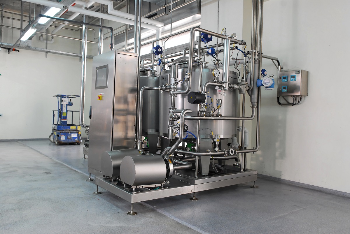
סמארטלוג'יק מעניקה שירותים המסתמכים על ידע וניסיון רב בעבודה עם מערכות מים, RO ,CIP, מזקקות, מערכות HVAC ,Utilities, ומודולים מוכנים סטנדרט S-88 שפיתחנו עבור מערכות אלו

ולידציה – Operation Qualification – OQ- part 2

ולידציה – Operation Qualification – OQ- part 2

Protocol Preparation Overview

This article provide overviews of the main test procedures and verification, and their purposes. This OQ procedure is generic, and relevance of the test procedures and verifications provided below depends on the composition of the system under validation

:Note

As mentioned in the previous artcle on OQ Protocol Contents, the final contents of the OQ protocol are tailored according to the type and size of the system under validation. Since this document is generic, it covers test procedures that may not be necessary in small or simple systems

:Where relevant, the OQ procedure may consists of five main test procedures

HMI Screen Test Procedure – intended to verify that the HMI screens provide the graphic design and functionality required for properly monitoring and controlling the environmental conditions in the user's

Parameters Lists Verification – intended to verify that the system parameters lists comply with the values specified in the SSO

Two types of parameters are checked

Process parameters

Alarm parameters

System Operation Test Procedure – intended to verify that system monitoring and control components are capable of maintaining the user's facility within specified temperature, humidity and pressure levels

System Alarms Test Procedure – intended to verify that when the specified temperature, humidity and pressure levels exceed its specified limits, an alarm message is displayed, and an SMS or e-mail notification is sent to relevant personnel

Test of HMI Compliance with 21 CFR Part 11 – This test is intended to verify that the HMI meets Valtech Cardio's URS regarding 21 CFR Part 11. These : requirements are divided into 5 categories for the sake of clarity

Security

Electronic Records

Audit Trail

Archive

Backup

 HMI Screen Test Procedure

This section includes specific test procedures for all the relevant HMI screens, where each test procedure serves to verify that the specific HMI screen provides the graphic design and functionality required for its intended purpose within the monitoring and controlling functions

Parameters Lists Verification

:This procedure covers the verifications of two types of parameters

Process parameters

Alarm parameters

Process Parameters List Verification

This procedure is intended to verify that:

The system enables to set the default values of the process set-points of each monitored environmental parameter.

The system provides automatically the corresponding low and high limits of these default values. These limit values are listed in  below

The system rejects all the SP values that exceed their allowed ranges, as specified in the SSO

Alarm Parameters List Verification

:This procedure is intended to verify that

The system enables to set the default values of the alarm set-points of each monitored environmental parameter

The system provides automatically the corresponding low and high limits of these default values

The system rejects all the SP values that exceed their allowed ranges, as specified in the SSO

 System Operation Test Procedure

This procedure is intended to verify that system monitoring and control components are capable of maintaining the user's facility within specified temperature, humidity and pressure levels. For this purpose, it is necessary to temporarily change set-points, in order to activate the control devices

System Alarms Test Procedures

This procedure is intended to verify that, when an environmental parameter value exceeds the specified normal range, the system reacts as specified in the SSO, by providing a specified alarm indication, a relevant e-mail alarm message, and relevant records in the Current Alarms and Historical Alarms screens

Test of HMI Compliance with 21 CFR Part 11

This test is intended to verify that the HMI meets the user's URS regarding 21 CFR Part 11. These requirements are divided into 5 categories for the sake of :clarity

Security

Electronic Records

Audit Trail

Archive

Backup


ולידציה – GAMP – Test Example – part 1

Good Automated Manufacturing Practice (GAMP) – Test Example

Testing Process Automation Systems

This article cover  the first part of  our  Good Automated Manufacturing Practice (GAMP) test example.

                                     Definitions

This section provides brief descriptions of three different types of process control systems.

                  Configurable Equipment

Configurable Equipment is the collective name given to simple configurable instruments/ devices, such as 3-term controllers, check scales, bar code readers, etc. Their functionality depends on that their configuration setup meets the process requirements. The software (SW) components of these systems are typically defined as GAMP SW Category 2.

                    Embedded Systems

Embedded Systems is the collective name for systems with a greater degree of configuration and programmability. Devices such as Integrated Circuits (ICs) with configuration setups and Programmable Logic Controllers (PLCs), which are supplied as an integral part to an item of process equipment, e.g., PLCs controlling a centrifuge or packaging machine, or IC embedded in High Performance Liquid Chromatography (HPLC) systems. Embedded Systems typically contain SW components belonging to multiple GAMP categories.

                 Stand-Alone Systems

Stand-Alone Systems is the collective name for large programmable control systems having distributed functionality across a network, e.g., Distributed Control Systems (DCSs), and Supervisory Control and Data Acquisition (SCADA). They are engineered as an entity to control a complete plant. Stand-Alone Systems typically contain SW components belonging to multiple GAMP categories.

                      Testing and the GAMP Life Cycle 

     Stand-Alone Systems

A process automation system developed for a new application typically requires some or all of the following test phases:

Suppliers Module Testing

Suppliers Module Integration Testing

Suppliers Integration Testing

Factory Acceptance Test (FAT)

Site Acceptance Test (SAT)

Installation Qualification (IQ)

Operation Qualification (OQ)

Performance Qualification (PQ)

The exact combination of testing required for a particular system should reflect its complexity, the maturity of its underlying SW and hardware (HW) elements, and the risk impact on product quality, patient safety and data integrity. Collectively these will determine the risk priority. The phrase 'low risk' should be understood as 'having a low risk priority, as determined by a formal risk assessment'.

Testing of modifications, patches or upgrades should be related to the risk priority of the change. For example, it may be appropriate for parameter changes to be applied directly to the production environment, assuming that the system have been range checked for such parameter.

End of ולידציה – GAMP – Test Example – part 1

אוטומציה ובקרה – איך מכינים HMI לבדיקת לוח בקרה

אוטומציה ובקרה – איך מכינים HMI  לבדיקת לוח בקרה בצורה הטובה ביותר

מהנדסי סמארט לוג'יק מסבירים איך להכין ממשק משתמש קל ונח לבדיקת לוחות בקרה וחשמל באמצעות Cimplicity.

Electrical cabinets Testing 1

Electrical cabinets Testing 1

להדרכה בנושא איך גורמים ל HMI לעבוד עם הרשאות ווינדוס לחץ כאן

בקרה ואוטומציה ליט"אות -HVAC / AHU control

בקרה ואוטומציה ליט"אות -HVAC / AHU control

HVAC stands for Heating, Ventilating and Air Conditioning. AHU stands for Air Handling Unit.

HVAC and AHU control systems provide centralized monitoring and control of these systems, designed to maintain selected rooms in research and production facilities within specified pressure, temperature and humidity levels. This is achieved by operating and monitoring active components or actuators, and by monitoring environmental conditions, such as pressure, temperature and humidity, using corresponding sensors located in the HVAC and AHU system and the selected rooms.

Smartlogic has an extensive knowledge and experience in HVAC & Ahu systems.

The monitored values in HVAC and AHU systems and rooms are analyzed and processed by one or more controllers, such as programmable logic controllers (PLCs) or direct digital controllers (DDCs), which control the system accordingly in conjunction with an HMI installed on a PC connected to the PLCs or DDCs. The levels of the environmental conditions are compared to set-points (SPs) that are displayed and can be determined using human-machine interface (HMI) screens.

The level adjustments of the environmental conditions, such as pressure, temperature and humidity are performed using temperature control valves, electrical chillers and heaters, blowers, differential pressure switches, motorized flow dampers, etc. Fault switch, such as temperature, pressure and humidity switches, and fire alarm switches in HVAC/AHU systems provide alarm indications in case of failures.

The PLCs or DDCs currently used to control HVAC and AHU devices, such as valves, and heaters, receive analog and digital inputs from the sensors and devices installed in HVAC and AHU systems and, according to control logic, provide analog or digital outputs to control the devices.

An example of a device installed in HVAC and AHU systems, and controlled by PLCs or DDCs is a chiller.

Example – Chiller Control

A chiller is a machine that removes heat from a liquid via a vapor-compression or absorption refrigeration cycle. This liquid can then be circulated through a heat exchanger to cool air or equipment, as required.

Use in Air Conditioning

In air conditioning systems, chilled water is typically distributed to heat exchangers, or coils, in HVAC and AHU systems, or other type of terminal devices which cool the air in its respective space(s), and then the chilled water is re-circulated back to the chiller to be cooled again. These cooling coils transfer sensible heat (heat exchanged by a body thermodynamic system that has as its sole effect a change of temperature) and latent heat (heat released or absorbed by a body or a thermodynamic system during a process that occurs without a change in temperature) from the air to the chilled water, thus cooling and usually dehumidifying the air stream.

Use in Industry

In industrial application, chilled water or other liquid from the chiller is pumped through process or laboratory equipment. Industrial chillers are used for controlled cooling of products, mechanisms and factory machinery in a wide range of industries. They are often used in the plastic industry in injection and blow molding, metal working cutting oils, welding equipment, die-casting and machine tooling, chemical processing, pharmaceutical formulation, food and beverage processing, paper and cement processing, vacuum systems, X-ray diffraction, power supplies and power generation stations, analytical equipment, semiconductors, compressed air and gas cooling. They are also used to cool high-heat specialized items such as MRI machines and lasers, and in hospitals, hotels and campuses.

Chillers for industrial applications can be centralized, where a single chiller serves multiple cooling needs, or decentralized where each application or machine has its own chiller. Each approach has its advantages. It is also possible to have a combination of both centralized and decentralized chillers, especially if the cooling requirements are the same for some applications or points of use, but not all.

Decentralized chillers are usually small in size and cooling capacity, while centralized chillers generally have larger capacities.

Chilled water is used to cool and dehumidify air in mid- to large-size commercial, industrial, and institutional facilities. Water chillers can be water-cooled, air-cooled, or cooled by evaporation. Water-cooled chillers incorporate the use of incorporate cooling towers which improve the chillers' thermodynamic effectiveness as compared to air-cooled chillers. Chillers cooled by evaporation offer higher efficiencies than air-cooled chillers but lower than water-cooled chillers.

Water-cooled chillers are typically intended for indoor installation and operation, and are cooled by a separate condenser water loop and connected to outdoor cooling towers to expel heat to the atmosphere.

Chillers cooled by air and evaporation are intended for outdoor installation and operation. Air-cooled machines are directly cooled by ambient air being mechanically circulated directly through the machine's condenser coil to expel heat to the atmosphere. Machines cooled by evaporation are similar, except they implement a mist of water over the condenser coil to aid in condenser cooling, making the machine more efficient than a traditional air-cooled machine.

Smartlogic has an extensive knowledge and experience in HVAC & Ahu systems.

אוטומציה ובקרה – חיבור הציוד לתקשורת SATEC

אוטומציה ובקרה – חיבור הציוד לתקשורת SATEC

 במאמר הבא נסקור את הייחודיות של מד ההספק של SATEC וכיצד ניתן להתחבר באמצעותו לרשתות תקשורת

כל דגמי Powermeter (מד הספק) של  SATEC העכשוויים מצוידים באחד או שני פורטים לתקשורת סריאלית המבודדים באופן אופטי. על כן הם מאפשרים פעילות בסוגים שונים של רשתות תקשורת, כולל אלו עם הפרעות של מתח גבוה ושדות מגנטיים.

פורט תקשורת תומך בממשקים סטנדרטיים מסוג   RS-232 eia, RS-422 או RS-485 (לפי בחירת המשתמש או היצרן), שמאפשר חיבור למחשב,PLC* – Programmable Logic Controller או מודם.

התקשורת פועלת במתכונת אדון-עבד (Master-Slave), כאשר המחשב המארח (host) פועל כאדון והמכשיר הנשלט פועל כעבד, ז"א, המחשב משדר בקשות למכשיר שמגיב למחשב; אבל המכשיר לא משדר מידע למחשב ביוזמתו. המחשב המארח סוקר את המכשיר כדי לקבל נתוני מדידה, או כדי לקרוא או לתכנת את הפרמטרים בקונפיגורציה של ה- Powermeter.

חיבורים מסוג multi-drop

מכשירי SATEC ניתנים לשימוש ברשתות מסוג multi-drop. המכשירים מקושרים לרשת דרך פורטים לתקשורת מסוג RS-422 או RS-485. שני פורטים אלו הם סטנדרטיים לממשקים דיפרנציאלים סריאליים (serial differential interface standards). מכיוון שמשתמשים במד דיפרנציאלי, הרעש ברשת כמעט מושתק.

בסטנדרט RS-422, המכשירים מקושרים לרשת דרך שני זוגות חוטי חשמל, זוג אחד לצורך שידור והשני לקליטה (full duplex).

בסטנדרט RS-485, המכשירים מקושרים לרשת דרך זוג אחד של חוטי חשמל, כאשר הזוג הבודד משמש שידור וגם לקליטה (half duplex), ז"א, המשדר והמקלט של המכשיר מחוברים במקביל (in parallel).

הרשת מחוברת לפורט קישור (מסוג RS-422 או RS-485) של מחשב (או PLC) שמשמש כמארח מקומי (local host), או לפורט קישור מחשבי מסוג RS-232 דרך ממיר . RS-232של SATEC. ממיר זה תומך בעד 32 מכשירים ומספק גילוי נתונים אוטומטי automatic data detection)), ללא צורך ב-RTS  חיצוני. המרחק בין הממיר והמכשיר RS-232 יכול להגיע עד 15 מטר. ניתן לחבר מחשב שמשמש כמארח מקומי לרשת דרך ממיר RSC-232 ושני מודמים. הממיר והמודם הראשון מותקנים ביחד עם המכשירים, והמודם השני עם המחשב.

חיבורי תקשורת

ניתן לחבר עד 32 מכשירים לרשת תקשורת מסוגmulti-drop  RS-422/RS-485, שמורכבת מזוג כבלים עם זוגות חוטי חשמל מפותלים ומוגנים (עבור RS-485: 2 זוגות, אחד פעיל ואחד רזרבי; עבור RS-422: 3 זוגות, 2 פעילים ואחד רזרבי). האורך הכולל של הכבל יכול להגיע עד 1200 מטר.

הכבל מורכב מקטעים בין המכשירים. ציפוי ההגנה (shield) של כל קטע כבל מסוג RS-422/RS-485 חייב להיות מחובר לאדמה באחד מקצותיו בלבד. וודא שהפולריות נכונה כאשר אתה מחבר את הטרמינלים (+) ו- ( ) של כל פורט מסוג RS-422/RS-485.

חוטי החשמל בשימוש חייבים להיות בגדלים ביןAWG  22 ו- AWG 12 (mm2 3.30.3-).

מומלץ להשתמש ברצועת טרמינל בכל חיבור של מכשיר לרשת, כדי לאפשר פירוק קל של מכשיר במידת הצורך.

קונפיגורציות של חיווט

רשת מסוג  multi-dropחייבת קונפיגורציה של נקודה-לנקודה (point-to-point configuration), ז"א, הטרמינלים (+) ו- ( -) של כל מכשיר חייבים להיות מחוברים לטרמינלים המתאימים של המכשיר הבא. מומלץ להשתמש בשיטת חיווט בקו ישר. חייבים להימנע מכל חיבור עם ענף בקו העיקריmain bus) ), כגון שיטות כוכב (star) ו-T  (tee); במקרים אלו יווצרו השתקפויות (reflections) של אותות שעלולות לגרום להתאבכות (interference) ראה איורים 1-4 (1-4Figures ).

כל נקודה סופית בקו העיקריmain bus) ) חייבת להסתיים עם נגד של1/4  ווט (Watt). נגדים אלו מצמצמים את השתקפויות Aעלולים לשבש את אותות הנתונים על הקו. נגדים אלו מחוברים בין הטרמינלים (+) ו- (- ) של המכשירים בכל קצה של הקו העיקרי. (כאשר משתמשים בממיר RSC-232 בחיבור למחשב, הנגד לא ישים מכיוון שהוא כבר מחובר בתוך הממיר). ערך הנגד חייב להתאים לאימפדנס הקווי (line impedance) של הכבל בשימוש, הערך האופייני נע בין 200 ו- 500 אוהם (Ohm).

רשתות תקשורת מסוג single-drop

מכשיר אחד יכול להתחבר למחשב מארח (computer host) אחד או לפורט קישור של מודם RS-232.

החיבור מחייב כבל עם זוגות חוטי חשמל מפותלים ומוגנים (3 זוגות: אחד פעיל, אחד מחודר לאדמה ואחד רזרבי). אורך יכול להגיע עד 15 מטר ניתן להאריך את המרחק הזה תוך שימוש בקצב שידור baud נמוך יותר, כבלים עם ציפוי ההגנה (shielded) או משחזר (repeater).

חוטי החשמל בשימוש חייבים להיות בגודלAWG  24 (mm2 0.5).

פרוטוקולים של תקשורת

כל מכשירי SATEC תומכים לפחות בשני פרוטוקולים: ASCII ו- Modicon Modbus RTU. שניהם פרוטוקולים פתוחים שניתנים לשימוש ע"י תוכנה של מארח ששייך לגוף שלישי  (third-party host-based software) נגישים לכל הנתונים ורגיסטרים של קונפיגורציה (registers configuration) של Powermeter.

מכשירים רבים של SATEC תומכים גם בפרוטוקול DNP3.0.

*סמארט לוג’יק משתמשת בבניית מערכות אוטומציה ובקרה בבקרים של חברת Siemens  וחברת אלן ברדלי – Allen-Bradley

דוגמאות ל- PLCs  בשימוש סמארטלוג’יק:

6XV1830-0EH10, 6ES7131-4BF00-0AA0, 6ES7193-4CA40-0AA0, 6ES7134-4GD00-0AB0, 6ES7193-4CA40-0AA0, 6ES7138-4CA01-0AA0, 6ES7193-4CC20-0AA0, 6ES7590-1AB60-0AA0, 6ES7511-1AK00-0AB0, 6ES7954-8LP01-0AA0, 6ES7155-6AU00-0BN0, 1746-NO4V, 1769-L16ER-BB1B


אוטומציה ובקרה – מערכות SCADA ו- DCS

אוטומציה ובקרה – מערכות SCADA ו- DCS

שתי מערכות חשובות בתחום מערכות בקרה תעשייתיות Industrial Control System – ICS – הן:

  • Supervisory Control and Data Acquisition – SCADA
  • Distributed Control System – DCS


SCADA היא מערכת שפועלת בעזרת אותות מקודדות דרך ערוצי תקשורת ומספקת בקרה על ציוד בשלט רחוק (תוך שימוש אופייני בערוץ תקשורת אחד עבור תחנה מרוחקת אחת). מערכת הבקרה ניתנת לשילוב עם מערכת להשגת מידע ע"י הוספת שימוש באותות מקודדות דרך ערוצי תקשורת להשגת מידע על הסטטוס של הציוד המרוחק לצורך תצוגה או רישום של הפונקציות.

מערכת  SCADAכוללת בדרך כלל את התת-מערכות הבאות:

  • ממשק אדם-מכונה (HMI – Human-Machine Interface), שמציג מידע על התהליך למפעיל, וכך מאפשר למפעיל לנתר ולבקר את התהליך.
  • מערכת פיקוח, שצוברת מידע על התהליך ושולחת הוראות כדי לבקר את אותו תהליך.
  • יחידות מסוף רחוקות RTUs) – Remote Terminal Units ), שמתחברות לגששים (sensors), ממירים את אותות הגששים לנתונים דיגיטליים, ושולחים את הנתונים הדיגיטליים למערכת הפיקוח.
  • בקרים לוגיים שניתנים לבקרה (PLCs – Programmable Logic Controllers ), שמשמשים כמתקני שדה, מכיוון שהם יותר כלכליים, מגוונים, גמישים וניתנים לתצורה (configuration) מיחידות RTU בשימושים מיוחדים.
  • תשתית תקשורת, שמקשרת את מערכת הפיקוח ליחידות RTU.


DCS היא מערכת בקרה עבור תהליך או מתקן, שבה רכיבי הבקרה ממוקמים בפיזור במערכת המבוקרת. מערך זה מבדיל את ה- DCS ממערכות לא מפולגות, שמשתמשות בבקר יחיד במיקום מרכזי. DCS משתמשת בצורה אופיינית במעבדים (processors) מותאמים למשימה, שמאורגנים בהיררכיה ומקושרים ע"י רשתות תקשורת לצורך ניתור ובקרה.


ההבדלים העיקריים ביןSCADA  ו- DCS הם:

  • SCADAמותאמת להשגת מידע, בעוד ש- DCS מותאמת לבקרת תהליך.
  • SCADA מונעת לצורך אירוע (event), בעוד ש – DCS מונעת לצורך תהליך (process).
  • SCADA עדיפה לאפליקציות מפוזרות במיקומים גאוגרפיים נרחבים, בעוד ש- DCS משמש בד"כ לטיפול בתהליכים שמתנהלים במקום אחד.
  • SCADA אמורה לתפקד למרות תקלה בתחום התקשורת, בעוד שתחנות מפעילי ה- DCS תמיד מחוברות לכניסה/יציאה (I/O -Input/Output).

לחברת סמארט לוג'יק צוות מומחים בעלי שם וניסיון רב,  דרך שיטות עבודה מתקדמות הדוגלת במודולאריות וסדר, פיתחנו בסמארט לוג'יק שיטה המאפשרת השלמת פרויקטים מורכבים, יעילים ואיכותיים תוך   שמירה על לוח זמנים קצר במיוחד ומחיר תחרותי.  החברה מספקת תכנון והקמת מערך אוטומציית בקרה של מתקן יצור שלם, בקרה ואוטומציה למערכות טיפול במים, בקרות למערכות חימום, אוורור ומיזוג אוויר  (תמונה) (HVAC) תואמים את דרישות המנהל האמריקאי (FDA) ועוד.


אוטומציה ובקרה – העלאת תוכנה מבקר סימנס

Batch Control ANSI/ISA-88 -S-88 – בקרת אצווה

אוטומציה ובקרה – Batch Control ANSI/ISA-88 – S-88 – בקרת אצווה

הקיצור S-88  מסמל את התקן ANSI/ISA-88 – S88. תקן זה מתייחס לבקרת אצווה Batch Control, ומהווה גישה תכנונית לתיאור ציוד ותהליך תכנון. תקן זה לא נועד לתוכנה בלבד; אלא משמש גם לתהליכים ידניים. התקן אושר ע"י ISA  ב- 1995 ועודכן ב- 2010.

סמארטלוג'יק מתמחה בתכנון תהליך בתקן S-88 מאפיון  Control-Modules דרך Equipment modules וכלה בפאזות תהליכיות. שירותי החברה מסתמכים על ידע וניסיון רב בעבודה עם מערכות מים, RO ,CIP, מזקקות, מערכות HVAC ,Utilities, ומודולים מוכנים סטנדרט S-88 שפיתחנו עבור מערכות אלו.

הגדרת ISA

 International Society of Automation – ISA הינה אגודה טכנית ללא מטרות רווח, מיועדת למהנדסים, טכנאים, אנשי עסקים, מחנכים וסטודנטים, שעובדים, לומדים או מעוניינים באוטומציה תעשייתית ועיסוקים מקושרים לנושא, כגון מכשור.

 ISA כוללת תחומים טכניים והנדסיים רבים, והינה אחת מהארגונים המובילים בעולם בקביעת סטנדרטים והדרכת אנשי מקצוע בתעשייה בנושא אוטומציה.

הגדרת ANSI

American National Standards Institute –  ANSI הינה ארגון פרטי ללא מטרות רווח שמפקח על פיתוח תקנים מוסכמים בהתנדבות, עבור מוצרים, שירותים, תהליכים, מערכות וכוח אדם בארה"ב. ארגון זה גם מתאם בין תקנים אמריקאים ובינלאומיים, כך שמוצרים אמריקאים יוכלו להיות משווקים בכל העולם.

ANSI מאשרת תקנים מפותחים ע"י נציגים של ארגונים, סוכנויות ממשלתיות, קבוצות צרכנים, חברות, וגופים אחרים. תקנים אלו מבטיחים שתכונות וביצועי המוצרים הם אחידים, שהציבור משתמש באותם הגדרות ומינוחים, ושהמוצרים נבדקים באותה צורה. ANSI גם מספקת אישורים לארגונים שמסמיכים מוצרים או כוח אדם בהתאם לדרישות מוגדרות בתקנים בינלאומיים.

בקרת אצווה ANSI/ISA-88 – S-88

כללי

ועדת ANSI/ISA-88 פרסמה סדרת תקנים בנושא בקרת אצווה במערכות אוטומציה תעשייתיות.

תקן ,ANSI/ISA-88.00.01-2010, Batch Control Part 1: Models and Terminology מספק דגמים ומינוחים תקניים (סטנדרטיים) להגדרת דרישות בקרה עבור מפעלים שמייצרים אצוות.

תקן ANSI/ISA-88.00.02-2001, Batch Control Part 2: Data Structures and Guidelines for Languages,  מגדיר דגמים של נתונים(data)  שמתארים בקרת אצווה כפי שהיא משמשת במערכות אוטומציה תעשייתיות, מבני נתונים שמאפשרים קידום תקשורות פנימיות וגם בין יישומי בקרת אצווה שונים, והנחיות לגבי שפות שמייצגות מתכונים (recipes).

תקן ANSI/ISA-88.00.03-2003, Batch Control Part 3: General and Site Recipe Models and Representation,  מגדיר דגם עבור מתכונים כלליים ומקומיים; פעילויות שמתארות את שימוש המתכונים הכלליים והמקומיים במסגרת חברה אחת ובין חברות שונות; ייצוג מתכונים כלליים ומקומיים; ודגם נתוני מתכונים כלליים ומקומיים.

תקן ANSI/ISA-88.00.04-2006, Batch Control Part 4: Batch Production Records,  מספק הגדרה מפורטת עבור רישומי ייצור אצוות, וקובע דגם ייחוס לפיתוח אפליקציות לאחסנת ו/או המרת רישומי ייצור אצוות. יישומים מבוססים על תקן זה מאפשרים אחזור, ניתוח ודיווח של רישומי ייצור אצוות נבחרים.

ייעוד והיקף S-88

S-88 מיועד לאספקת תקנים והרגלי עבודה מומלצים לתכנון והגדרת מערכות בקרת אצווה בתעשיות עם בקרת תהליכים.

S88 מספק הנחיות לפיתוח וספציפיקציות של מערכות בקרת אצווה. הנחיות אלו גם מבוססות על תקנים והרגלי עבודה מומלצים ע"י ISA וארגונים אחרים, וגם משלים את התקנים וההמלצות הנ"ל. הנושאים שיילקחו בחשבון להכללתם ע"י הועדה הם:

  • הגדרת מונחים ספציפיים למערכות בקרת אצווה, שתעודד הבנה בין יצרנים ומשתמשים.
  • הגדרת שפה סטנדרטית למבנה נתונים של בקרת אצווה, שתקל על תכנות, על פעילויות קונפיגורציה, ועל תקשורת בין הרכיבים השונים של המערכת.
  • הגדרת מבנה נתונים סטנדרטי  למערכות אצווה, שיקל על פעילויות תקשורת הנתונים במסגרת אדריכלות המערכת.
  • קביעת אדריכלות בקרת אצווה סטנדרטית שמגדירה את הדגמים הפיזי ופונקציונאלי. הדגם הפיזי הוא המבנה ההיררכי שמקשר בין ציוד הבקרה לבין תקשורות הנתונים הנחוצות לאזורים הפיזיים המעורבים בבקרת האצווה. הדגם הפונקציונאלי מציג את הקישורים בין חמשת סוגי הבקרה: ניהול המתכונים, לו"ז, בקרה סדרתית(sequential) , בקרה תקנית (regulatory), מערכות חיגור (interlock)
  • לבטיחות.

סמארטלוג'יק מבצעת פרויקטי אוטומציה ובקרה מודולארית למתקני יצור תוך שימוש בתקן S-88

אוטומציה ובקרה – תזמון הרצת סקריפטים בסימפליסיטי