Smartlogic

ולידציה – URS – Regulatory & HMI Requirements

ולידציה – URS – Regulatory & HMI Requirements

 This article was written by Iian Shaya, validation,automation and control expert

Regulatory Requirements

These requirements cover all the FDA specifications regarding the system compliance with the 21 CFR Part 11 definitions, and also with usual validation documentation demands

Computerized system compliance with 21 CFR Part 11 definitions, such as the system access control by the user's managing personnel, who shall be responsible for the content of the electronic records (ERs) contained in the system

System capability of restricting logical access to the system according to specified authorization levels.

Access to the system allowed only by user ID and a specific password

System capability to record the values, alarms, user changes and any other events, and provide readable forms and reports of ER data

Storage of historical events, current alarms and historical alarms data records on the computerized system database

Data display to the user in "view only" mode, so the user cannot alter or delete data/records

Provision of user's capability to backup data daily, weekly and monthly, according to his procedures, to ensure protection of the records and to enable their accurate and ready retrieval throughout the records retention period.

Provision by the supplier of a project plan and quality assurance (QA) processes during development and the testing stages as part of his QA systems

Provision by the supplier of the following documents

Functional Requirements Specification –FRS.

Functional Design Specification – FDS

IO List

Schedule of System Operation – SSO

Installation Qualification (IQ) protocol.

Operation Qualification (OQ) protocol

Performance Qualification (PQ) protoco
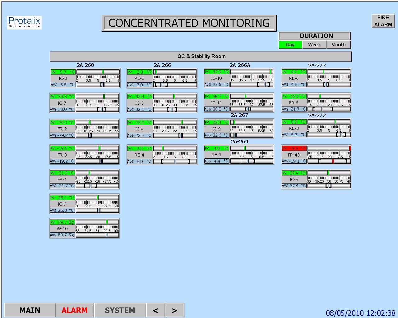
HMI Requirements

These requirements cover the provisions demanded from the HMI screens, regarding proper graphic design and functionality for controlling and monitoring the system, as specified in customer's contract with the supplier

:Note

The final contents of the URS and FRS are tailored according to the type and size of the system under validation. Since the URS and FRS regarded herein are generic, they include requirements that may not be necessary in small or simple systems

 This article was written by Iian Shaya, validation,automation and control expert

ולידציה – URS Contents

ולידציה – URS Contents

 This article was written by Iian Shaya, validation,automation and control expert

A URS usually presents the user's requirements for installing and operating a system designed to monitor and control specified conditions at its facility

:The user's requirements may be divided into 4 categories

Installation Requirements

Operation Requirements

Regulation Requirements

HMI Requirements

Installation Requirements

These requirements are intended to cover all the issues regarding system installation to ensure its proper functionality and reliability. Examples of this type of requirements are:

List of required hardware (HW) components, such as system PC, Programmable Logic Controller* (PLC), and varied environmental conditions sensors and control devices

Labeling and identification requirements for each HW component

Requirements for the software (SW) programs installed on the system PC

Storage capacity

Required connections to various types of sensors, communication units, temperature, humidity and pressure transmitters, illumination devices, etc

Communication compatibility with equipment already installed at the user's facility without extra sensors

Operation Requirements

These requirements cover all the operations that the system must be capable of performing. Examples of this type of requirements are

Environmental conditions (such as pressure, temperature and humidity) to be monitored and controlled

Type of systems to be monitored and controlled, such as Heating, Ventilation and Air Conditioning (HVAC) system, types of sensors, etc

Computerized system capabilities and starting conditions

System capabilities to recover from failures

Internal tests to be performed regularly, and alarm indications to be issued in case of failure

Provision of current and historical alarms regarding all parameters in any case of deviation from the limits specified in the system

System real-time screens display capabilities

Provision of the following data and HMI displays

Synoptic screens for displaying online values and status

Data logging and storage of historical trends, events and alarms

Tabular screens for displaying events and alarms

Graphical screens for displaying trends

Display of the following information for each alarm

Status – new/acknowledged alarm

Time at which the alarm was activated

Parameter/Tag/Name of the module that activated the alarm

Alarm Description

Alarm Priority

Display of alarms to warn the user, collect alarm history, and enable the user to view current and historical alarms. The system alarms shall include

Component malfunction/failure

Irregularity in parameter reading – such as disconnection of communication lines

Parameters values exceeding the high/low parameter limits

Deviations of system operation from predefined parameters/operations

Capability of configuring the graphs parameters according to

Date and time

Measured parameters

Predefined number of displayed parameters

Trend graphs with maximum and minimum allowed limits of the monitored parameters

Logging interval defined by the user and configured by the supplier

Capability of authorized user's personnel to define low and high limits and delay time for each alarm parameter

  .On URS regulatory & HMI Requirements you can find out in our this link: URS – Regulatory & HMI Requirements

*Here are some examples of the PLCs used by smartlogic: 6XV1830-0EH10, 6ES7131-4BF00-0AA0,6ES7193-4CA40-0AA0,6ES7134-4GD00-0AB0,6ES7193-4CA40-0AA0, 6ES7138-4CA01-0AA0,6ES7193-4CC20-0AA0, 6ES7590-1AB60-0AA0, 6ES7511-1AK00-0AB0, 6ES7954-8LP01-0AA0,6ES7155-6AU00-0BN0

 This article was written by Iian Shaya, validation,automation and control expert

ולידציה – FRS for Compliance with 21 CFR Part 11

Functional Requirements Specification -FRS Regarding Requirements for Compliance with 21 CFR Part 11

This FRS presents SmarLogic's functional requirements in response to the User Requirements Specification (URS) . These functional requirements should be met in order to ensure  Control and Monitoring System complies with 21 CFR Part 11.

This FRS must be considered for the system design, build, installation, operation and testing requirements, and for traceability purposes along the product life cycle up to the Operational Qualification (OQ) stage.

                              Responsibility

The Validation Engineer is responsible for writing this protocol. The Control, Automation & Validation Engineer is responsible for ensuring the preparation and approval of this protocol.

The Control Engineer, Division Process Engineer and QA Manager are responsible of approving this document before development and on-site implementations.

The following sections list the functional requirements determined by the relevant groups of the system upgrading. Each functional requirement number is followed by the corresponding user requirement paragraph number for design qualification purpose

                            Glossary

ER – Electronic Record

DB – Database

FRS – functional requirements Specification

HMI – Human/Machine Interface

HSP – High Set-Point

HW – Hardware

IQ –  Installation Qualification

LSP –  Low Set-Point

OQ – Operational Qualification

OS – Operating System

PLC ָָ*- Programmable Logic Controller

QA – Quality Assurance

SCR – Screen

SOP – Standard Operating Procedures

SP – Set-Point

SSO – Schedule of System Operation

SW – Software

TP – Test Point

URS – User Requirements Specification

Requirements for Meeting 21 CFR Part 11

                        Top-Level Requirements

This section covers the proposed solutions for meeting 21 CFR Part 11 presented in the URS for a new WinCC HMI System. This system must allow the :following five main functionalities

Ensure the system integrity

Control the access to the system by logical security

Audit events that create and modify electronic records

Apply electronic signatures to the system

Backup and archive data to ensure record integrity in case of failure

                      Detailed Requirements

This section describes SmartLogic's solutions that will meet the detailed requirements listed in the URS. These requirements are divided into 6 categories for the sake of clarity:

Electronic Records

Security

Audit Trail

Archive

Backup

* Here are some examples of the PLCs used by smartlogic: 6XV1830-0EH10, 6ES7131-4BF00-0AA0,6ES7193-4CA40-0AA0,6ES7134-4GD00-0AB0,6ES7193-4CA40-0AA0, 6ES7138-4CA01-0AA0,6ES7193-4CC20-0AA0, 6ES7590-1AB60-0AA0, 6ES7511-1AK00-0AB0, 6ES7954-8LP01-0AA0,6ES7155-6AU00-0BN0

ולידציה – Operation Qualification – OQ- part 2

ולידציה – Operation Qualification – OQ- part 2

Protocol Preparation Overview

This article provide overviews of the main test procedures and verification, and their purposes. This OQ procedure is generic, and relevance of the test procedures and verifications provided below depends on the composition of the system under validation

:Note

As mentioned in the previous artcle on OQ Protocol Contents, the final contents of the OQ protocol are tailored according to the type and size of the system under validation. Since this document is generic, it covers test procedures that may not be necessary in small or simple systems

:Where relevant, the OQ procedure may consists of five main test procedures

HMI Screen Test Procedure – intended to verify that the HMI screens provide the graphic design and functionality required for properly monitoring and controlling the environmental conditions in the user's

Parameters Lists Verification – intended to verify that the system parameters lists comply with the values specified in the SSO

Two types of parameters are checked

Process parameters

Alarm parameters

System Operation Test Procedure – intended to verify that system monitoring and control components are capable of maintaining the user's facility within specified temperature, humidity and pressure levels

System Alarms Test Procedure – intended to verify that when the specified temperature, humidity and pressure levels exceed its specified limits, an alarm message is displayed, and an SMS or e-mail notification is sent to relevant personnel

Test of HMI Compliance with 21 CFR Part 11 – This test is intended to verify that the HMI meets Valtech Cardio's URS regarding 21 CFR Part 11. These : requirements are divided into 5 categories for the sake of clarity

Security

Electronic Records

Audit Trail

Archive

Backup

 HMI Screen Test Procedure

This section includes specific test procedures for all the relevant HMI screens, where each test procedure serves to verify that the specific HMI screen provides the graphic design and functionality required for its intended purpose within the monitoring and controlling functions

Parameters Lists Verification

:This procedure covers the verifications of two types of parameters

Process parameters

Alarm parameters

Process Parameters List Verification

This procedure is intended to verify that:

The system enables to set the default values of the process set-points of each monitored environmental parameter.

The system provides automatically the corresponding low and high limits of these default values. These limit values are listed in  below

The system rejects all the SP values that exceed their allowed ranges, as specified in the SSO

Alarm Parameters List Verification

:This procedure is intended to verify that

The system enables to set the default values of the alarm set-points of each monitored environmental parameter

The system provides automatically the corresponding low and high limits of these default values

The system rejects all the SP values that exceed their allowed ranges, as specified in the SSO

 System Operation Test Procedure

This procedure is intended to verify that system monitoring and control components are capable of maintaining the user's facility within specified temperature, humidity and pressure levels. For this purpose, it is necessary to temporarily change set-points, in order to activate the control devices

System Alarms Test Procedures

This procedure is intended to verify that, when an environmental parameter value exceeds the specified normal range, the system reacts as specified in the SSO, by providing a specified alarm indication, a relevant e-mail alarm message, and relevant records in the Current Alarms and Historical Alarms screens

Test of HMI Compliance with 21 CFR Part 11

This test is intended to verify that the HMI meets the user's URS regarding 21 CFR Part 11. These requirements are divided into 5 categories for the sake of :clarity

Security

Electronic Records

Audit Trail

Archive

Backup


ולידציה – Operation Qualification – OQ- part 1

ולידציה – Operation Qualification – OQ- part 1

Protocol Preparation Overview

The Operation Qualification (OQ) protocol is part of the validation documentation that covers the verification of the proper operation of the system under validation in the user's facility. This OQ protocol is generic, and the system may include a PC with Human/Machine Interface (HMI), a Programmable Logic Controller* (PLC), pressure, temperature and humidity transmitters, and other monitoring and control components designed to maintain the user's facility in proper environmental conditions (temperature, pressure and humidity)

This OQ protocol is intended to verify that the system under validation operates according to the acceptance criteria specified in the Schedule of System Operation (SSO), and also meets the vendor's requirements and the user's specifications. It must be reviewed and approved prior to the OQ performance

OQ Protocol Contents

The OQ protocol is structured in a relatively standard fashion, with predetermined chapters and sections, where the final contents are tailored according to the type and size of the system under validation

:The chapters and sections of an OQ protocol are

Documents Verification – procedure intended to verify that all the documents required for performing the OQ procedure are approved and available

OQ Test Procedures – this is the main part of the protocol, and provides the description of the test procedures and the result tables for filling and approving the test results

: Note

As the final contents of the OQ protocol are tailored according to the type and size of the system under validation, and this document is generic, it covers test procedures that may not be necessary in small or simple systems

Documents Verification

:This procedure is intended to verify that all the documents required for performing the OQ procedure are approved and available. These documents are

Functional Requirements Specification (FRS)

Installation Qualification (IQ) Protocol

Piping and Instrumentation Drawing – P&ID

Input/Output (I/O) List

Schedule of System Operation (SSO)

OQ Test Procedures

This chapter contains all the test procedures or verification required to verify the system under validation is properly installed and can be properly operated according to the supplier's requirements and user's specifications

:Each test procedure or verification must include the same contents

Purpose or Objective

Procedure or Method

Acceptance Criteria

Test Results

*Here are some examples of the PLCs used by smartlogic: 6XV1830-0EH10, 6ES7131-4BF00-0AA0,6ES7193-4CA40-0AA0,6ES7134-4GD00-0AB0,6ES7193-4CA40-0AA0, 6ES7138-4CA01-0AA0,6ES7193-4CC20-0AA0, 6ES7590-1AB60-0AA0, 6ES7511-1AK00-0AB0, 6ES7954-8LP01-0AA0,6ES7155-6AU00-0BN0

ולידציה – Installation Qualification (IQ) Protocol

ולידציה – Installation Qualification (IQ) Protocol

Preparation Overview – part 1

The Installation Qualification (IQ) protocol is part of the validation documentation that covers the verification of the proper installation and operation of the system under validation in the user's facility. This IQ protocol is generic, and the system may include a PC with Human/Machine Interface (HMI), a Programmable Logic Controller (PLC), pressure, temperature and humidity transmitters, and other monitoring and control components designed to maintain the user's facility in proper environmental conditions.

The IQ protocol is designed to verify that the system under validation is properly installed and can be properly operated according to the supplier's requirements and the user's specifications. It must be reviewed and approved prior to the IQ performance.

                            Installation Qualification (IQ) Protocol Contents

The IQ protocol is structured in a relatively standard fashion, with predetermined chapters and sections, where the final contents are tailored according to the type and size of the system under validation.

:The IQ protocol includes the following chapters and sections

 Document Approvals – contains a table that lists the supplier's and user's personnel required to approve the protocol

Participants – contains a table with the supplier's and user's personnel that participate in the validation process and approve their participation

Responsibilities – lists the roles of supplier's and user's personnel responsible for writing and approving the protocol

Glossary – lists the acronyms used in the protocol

IQ Validation Approach – defines the scope of the IQ process, and the requirements for its successful completion

IQ Test Procedures – this is the main part of the protocol, and provides the description of the test procedures and the result tables for filling and approving the test results

IQ Approvals – contains a table with the user's personnel responsible for reviewing and approving the test results, summary reports and conclusions

Appendices – include validation deviation forms and the documentation list with all the documents and drawings relevant to the IQ process

This is the first part of  the preparation overview in Installation Qualification (IQ) protocol, the second part is  IQ Test Procedures which will be discus elaborately in our next article.

אוטומציה ובקרה – איך מכינים HMI לבדיקת לוח בקרה

אוטומציה ובקרה – איך מכינים HMI  לבדיקת לוח בקרה בצורה הטובה ביותר

מהנדסי סמארט לוג'יק מסבירים איך להכין ממשק משתמש קל ונח לבדיקת לוחות בקרה וחשמל באמצעות Cimplicity.

Electrical cabinets Testing 1

Electrical cabinets Testing 1

להדרכה בנושא איך גורמים ל HMI לעבוד עם הרשאות ווינדוס לחץ כאן

ולידציה – GAMP – Test Environments – Test Data Sets

ולידציה  Good Automated Manufacturing Practice – GAMP – Test Environments – Test Data Sets

Test data sets are often use where the test environment does no permit the use of real data for reasons of availability or confidentiality, or where the real data are not generic enough to cover certain test types (e.g., challenge testing at boundary conditions or stress testing).

                          Representative Test Environment

Test data should represent as close as possible the actual data to be operated on, in terms of volume and range of possible values (including invalid entries, to check that they can be correctly handled).

Differences between the proposed test data and the expected actual data should be detailed on the Test Specification or Protocol, and subject to impact assessment. If necessary, additional tests should be planned for the production environment in order to cover identified risk scenarios.

                         Control of Test Environment

Test data sets should be placed under configuration management and the version in use recorded.

For automatically generated data it may also be appropriate to control the utility used for generating the data, as well as the test data set

                         Removal from Production Environment

If the test data SW is added in the way that it may appear in the production environment, then, this should be documented a temporary modification to the production system. Removal of the temporary modification should be documented as well.

If the production environment includes automatic audit trailing, then it should be recognized that all audit trail entries from the testing process will remain.

                              Test User Accounts

Test user accounts are often used to permit testers to access the system at different levels, and ensure that activities carried out during testing are easily identified within any resulting audit trail.

                          Representative Test Environment

Where test user accounts are often used, these should be set up to represent each group of users within the system, including the corresponding authorizations. For multi-lingual system, test user accounts using foreign character sets should be included. Similarly, if existing individual accounts are used for testing, representatives from each group should be included.

                         Control of Test Environment

If test user accounts are used, then the setup of the accounts should be retained as part of the test documentation. Where there are issues of data confidentiality, controls should be exercised to ensure that the use of test accounts does not cause breaches of confidentiality.

                        Removal from Production Environment

If the test user accounts are added in the way that it may appear in the production environment, then, this should be documented a temporary modification to the production system. Removal of the temporary modification should be documented as well.

                            Test Documentation

The test environment includes documentation used during testing. This should always include the test documentation (Test Plans and Strategies, Protocols and Test Specifications, Test Cases and Test Scripts) and the controlling Design Specifications. It may also include operating procedures such as SOPs.

The test documentation should be controlled and recorded to a level of detail that would allow it to be retrieved as part of later review of the test results. This control would, at minimum, include the recording of current document version levels.

בקרה ואוטומציה ליט"אות -HVAC / AHU control

בקרה ואוטומציה ליט"אות -HVAC / AHU control

HVAC stands for Heating, Ventilating and Air Conditioning. AHU stands for Air Handling Unit.

HVAC and AHU control systems provide centralized monitoring and control of these systems, designed to maintain selected rooms in research and production facilities within specified pressure, temperature and humidity levels. This is achieved by operating and monitoring active components or actuators, and by monitoring environmental conditions, such as pressure, temperature and humidity, using corresponding sensors located in the HVAC and AHU system and the selected rooms.

Smartlogic has an extensive knowledge and experience in HVAC & Ahu systems.

The monitored values in HVAC and AHU systems and rooms are analyzed and processed by one or more controllers, such as programmable logic controllers (PLCs) or direct digital controllers (DDCs), which control the system accordingly in conjunction with an HMI installed on a PC connected to the PLCs or DDCs. The levels of the environmental conditions are compared to set-points (SPs) that are displayed and can be determined using human-machine interface (HMI) screens.

The level adjustments of the environmental conditions, such as pressure, temperature and humidity are performed using temperature control valves, electrical chillers and heaters, blowers, differential pressure switches, motorized flow dampers, etc. Fault switch, such as temperature, pressure and humidity switches, and fire alarm switches in HVAC/AHU systems provide alarm indications in case of failures.

The PLCs or DDCs currently used to control HVAC and AHU devices, such as valves, and heaters, receive analog and digital inputs from the sensors and devices installed in HVAC and AHU systems and, according to control logic, provide analog or digital outputs to control the devices.

An example of a device installed in HVAC and AHU systems, and controlled by PLCs or DDCs is a chiller.

Example – Chiller Control

A chiller is a machine that removes heat from a liquid via a vapor-compression or absorption refrigeration cycle. This liquid can then be circulated through a heat exchanger to cool air or equipment, as required.

Use in Air Conditioning

In air conditioning systems, chilled water is typically distributed to heat exchangers, or coils, in HVAC and AHU systems, or other type of terminal devices which cool the air in its respective space(s), and then the chilled water is re-circulated back to the chiller to be cooled again. These cooling coils transfer sensible heat (heat exchanged by a body thermodynamic system that has as its sole effect a change of temperature) and latent heat (heat released or absorbed by a body or a thermodynamic system during a process that occurs without a change in temperature) from the air to the chilled water, thus cooling and usually dehumidifying the air stream.

Use in Industry

In industrial application, chilled water or other liquid from the chiller is pumped through process or laboratory equipment. Industrial chillers are used for controlled cooling of products, mechanisms and factory machinery in a wide range of industries. They are often used in the plastic industry in injection and blow molding, metal working cutting oils, welding equipment, die-casting and machine tooling, chemical processing, pharmaceutical formulation, food and beverage processing, paper and cement processing, vacuum systems, X-ray diffraction, power supplies and power generation stations, analytical equipment, semiconductors, compressed air and gas cooling. They are also used to cool high-heat specialized items such as MRI machines and lasers, and in hospitals, hotels and campuses.

Chillers for industrial applications can be centralized, where a single chiller serves multiple cooling needs, or decentralized where each application or machine has its own chiller. Each approach has its advantages. It is also possible to have a combination of both centralized and decentralized chillers, especially if the cooling requirements are the same for some applications or points of use, but not all.

Decentralized chillers are usually small in size and cooling capacity, while centralized chillers generally have larger capacities.

Chilled water is used to cool and dehumidify air in mid- to large-size commercial, industrial, and institutional facilities. Water chillers can be water-cooled, air-cooled, or cooled by evaporation. Water-cooled chillers incorporate the use of incorporate cooling towers which improve the chillers' thermodynamic effectiveness as compared to air-cooled chillers. Chillers cooled by evaporation offer higher efficiencies than air-cooled chillers but lower than water-cooled chillers.

Water-cooled chillers are typically intended for indoor installation and operation, and are cooled by a separate condenser water loop and connected to outdoor cooling towers to expel heat to the atmosphere.

Chillers cooled by air and evaporation are intended for outdoor installation and operation. Air-cooled machines are directly cooled by ambient air being mechanically circulated directly through the machine's condenser coil to expel heat to the atmosphere. Machines cooled by evaporation are similar, except they implement a mist of water over the condenser coil to aid in condenser cooling, making the machine more efficient than a traditional air-cooled machine.

Smartlogic has an extensive knowledge and experience in HVAC & Ahu systems.

אוטומציה ובקרה – מערכות SCADA ו- DCS

אוטומציה ובקרה – מערכות SCADA ו- DCS

שתי מערכות חשובות בתחום מערכות בקרה תעשייתיות Industrial Control System – ICS – הן:

  • Supervisory Control and Data Acquisition – SCADA
  • Distributed Control System – DCS


SCADA היא מערכת שפועלת בעזרת אותות מקודדות דרך ערוצי תקשורת ומספקת בקרה על ציוד בשלט רחוק (תוך שימוש אופייני בערוץ תקשורת אחד עבור תחנה מרוחקת אחת). מערכת הבקרה ניתנת לשילוב עם מערכת להשגת מידע ע"י הוספת שימוש באותות מקודדות דרך ערוצי תקשורת להשגת מידע על הסטטוס של הציוד המרוחק לצורך תצוגה או רישום של הפונקציות.

מערכת  SCADAכוללת בדרך כלל את התת-מערכות הבאות:

  • ממשק אדם-מכונה (HMI – Human-Machine Interface), שמציג מידע על התהליך למפעיל, וכך מאפשר למפעיל לנתר ולבקר את התהליך.
  • מערכת פיקוח, שצוברת מידע על התהליך ושולחת הוראות כדי לבקר את אותו תהליך.
  • יחידות מסוף רחוקות RTUs) – Remote Terminal Units ), שמתחברות לגששים (sensors), ממירים את אותות הגששים לנתונים דיגיטליים, ושולחים את הנתונים הדיגיטליים למערכת הפיקוח.
  • בקרים לוגיים שניתנים לבקרה (PLCs – Programmable Logic Controllers ), שמשמשים כמתקני שדה, מכיוון שהם יותר כלכליים, מגוונים, גמישים וניתנים לתצורה (configuration) מיחידות RTU בשימושים מיוחדים.
  • תשתית תקשורת, שמקשרת את מערכת הפיקוח ליחידות RTU.


DCS היא מערכת בקרה עבור תהליך או מתקן, שבה רכיבי הבקרה ממוקמים בפיזור במערכת המבוקרת. מערך זה מבדיל את ה- DCS ממערכות לא מפולגות, שמשתמשות בבקר יחיד במיקום מרכזי. DCS משתמשת בצורה אופיינית במעבדים (processors) מותאמים למשימה, שמאורגנים בהיררכיה ומקושרים ע"י רשתות תקשורת לצורך ניתור ובקרה.


ההבדלים העיקריים ביןSCADA  ו- DCS הם:

  • SCADAמותאמת להשגת מידע, בעוד ש- DCS מותאמת לבקרת תהליך.
  • SCADA מונעת לצורך אירוע (event), בעוד ש – DCS מונעת לצורך תהליך (process).
  • SCADA עדיפה לאפליקציות מפוזרות במיקומים גאוגרפיים נרחבים, בעוד ש- DCS משמש בד"כ לטיפול בתהליכים שמתנהלים במקום אחד.
  • SCADA אמורה לתפקד למרות תקלה בתחום התקשורת, בעוד שתחנות מפעילי ה- DCS תמיד מחוברות לכניסה/יציאה (I/O -Input/Output).

לחברת סמארט לוג'יק צוות מומחים בעלי שם וניסיון רב,  דרך שיטות עבודה מתקדמות הדוגלת במודולאריות וסדר, פיתחנו בסמארט לוג'יק שיטה המאפשרת השלמת פרויקטים מורכבים, יעילים ואיכותיים תוך   שמירה על לוח זמנים קצר במיוחד ומחיר תחרותי.  החברה מספקת תכנון והקמת מערך אוטומציית בקרה של מתקן יצור שלם, בקרה ואוטומציה למערכות טיפול במים, בקרות למערכות חימום, אוורור ומיזוג אוויר  (תמונה) (HVAC) תואמים את דרישות המנהל האמריקאי (FDA) ועוד.