Smartlogic

ולידציה – URS Contents

ולידציה – URS Contents

 This article was written by Iian Shaya, validation,automation and control expert

A URS usually presents the user's requirements for installing and operating a system designed to monitor and control specified conditions at its facility

:The user's requirements may be divided into 4 categories

Installation Requirements

Operation Requirements

Regulation Requirements

HMI Requirements

Installation Requirements

These requirements are intended to cover all the issues regarding system installation to ensure its proper functionality and reliability. Examples of this type of requirements are:

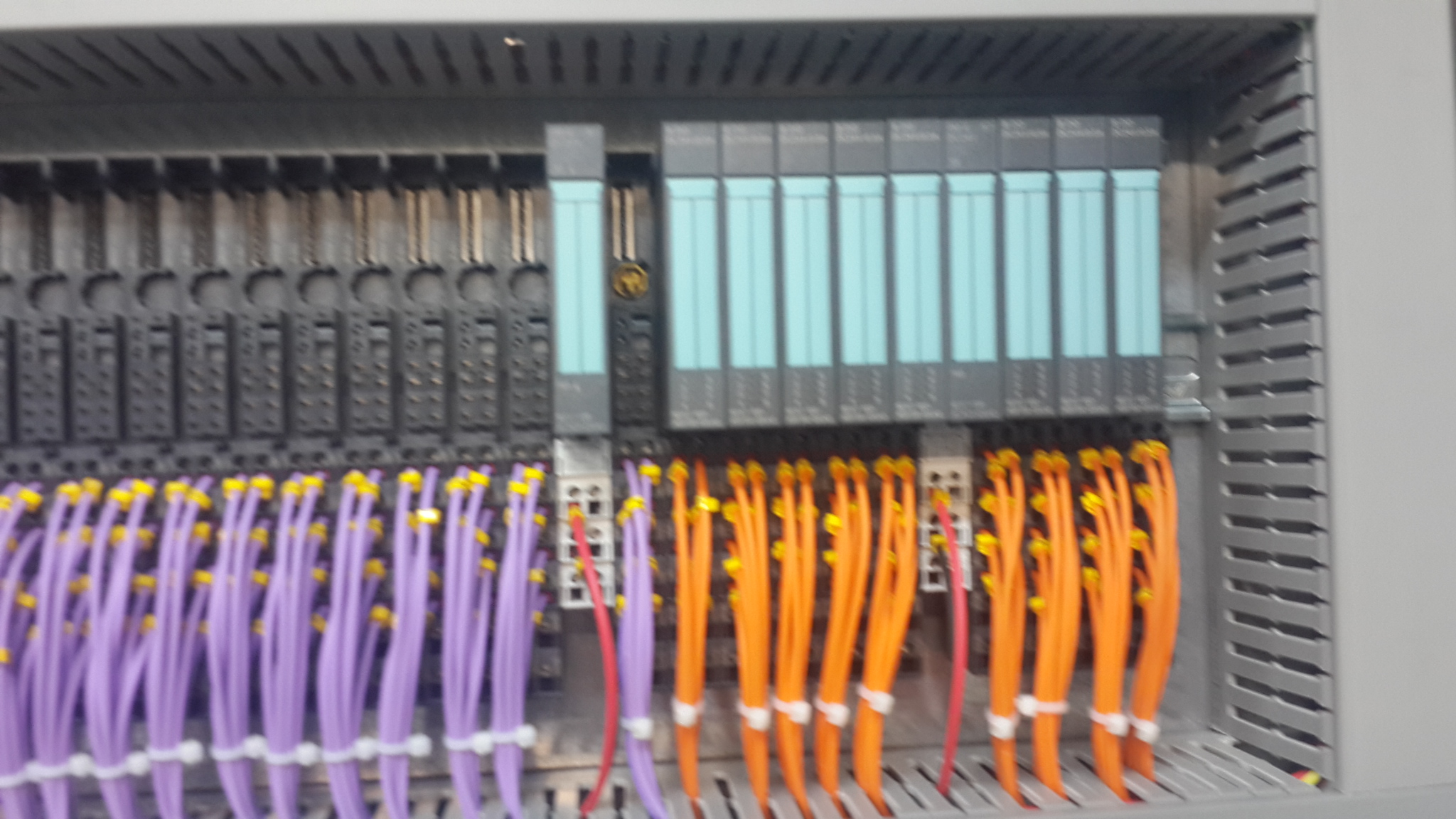
List of required hardware (HW) components, such as system PC, Programmable Logic Controller* (PLC), and varied environmental conditions sensors and control devices

Labeling and identification requirements for each HW component

Requirements for the software (SW) programs installed on the system PC

Storage capacity

Required connections to various types of sensors, communication units, temperature, humidity and pressure transmitters, illumination devices, etc

Communication compatibility with equipment already installed at the user's facility without extra sensors

Operation Requirements

These requirements cover all the operations that the system must be capable of performing. Examples of this type of requirements are

Environmental conditions (such as pressure, temperature and humidity) to be monitored and controlled

Type of systems to be monitored and controlled, such as Heating, Ventilation and Air Conditioning (HVAC) system, types of sensors, etc

Computerized system capabilities and starting conditions

System capabilities to recover from failures

Internal tests to be performed regularly, and alarm indications to be issued in case of failure

Provision of current and historical alarms regarding all parameters in any case of deviation from the limits specified in the system

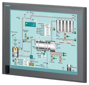
System real-time screens display capabilities

Provision of the following data and HMI displays

Synoptic screens for displaying online values and status

Data logging and storage of historical trends, events and alarms

Tabular screens for displaying events and alarms

Graphical screens for displaying trends

Display of the following information for each alarm

Status – new/acknowledged alarm

Time at which the alarm was activated

Parameter/Tag/Name of the module that activated the alarm

Alarm Description

Alarm Priority

Display of alarms to warn the user, collect alarm history, and enable the user to view current and historical alarms. The system alarms shall include

Component malfunction/failure

Irregularity in parameter reading – such as disconnection of communication lines

Parameters values exceeding the high/low parameter limits

Deviations of system operation from predefined parameters/operations

Capability of configuring the graphs parameters according to

Date and time

Measured parameters

Predefined number of displayed parameters

Trend graphs with maximum and minimum allowed limits of the monitored parameters

Logging interval defined by the user and configured by the supplier

Capability of authorized user's personnel to define low and high limits and delay time for each alarm parameter

  .On URS regulatory & HMI Requirements you can find out in our this link: URS – Regulatory & HMI Requirements

*Here are some examples of the PLCs used by smartlogic: 6XV1830-0EH10, 6ES7131-4BF00-0AA0,6ES7193-4CA40-0AA0,6ES7134-4GD00-0AB0,6ES7193-4CA40-0AA0, 6ES7138-4CA01-0AA0,6ES7193-4CC20-0AA0, 6ES7590-1AB60-0AA0, 6ES7511-1AK00-0AB0, 6ES7954-8LP01-0AA0,6ES7155-6AU00-0BN0

 This article was written by Iian Shaya, validation,automation and control expert

אוטומציה ובקרה – Create the Generic PLC Model

אוטומציה ובקרה –  Create the Generic PLC Model

PLC is a digital computer used for automation of elector mechanical processes, such as control of machinery on factory assembly lines.

PLCs are usually programmed using application software (SW) on personal computers (PCs). The PC is connected to the PLC through Ethernet, RS-232, RS-485 or RS-422 cabling. Most PLCs used by smartlogic when designing an automation and control systems are the Siemens PLCs and Allen Bradley‘s.The programming SW allows entry and editing of the ladder-style logic. Generally the SW provides functions for debugging and troubleshooting the PLC software, for example, by highlighting portions of the logic to show current status during operation or via simulation. The SW will upload and download the PLC program, for backup and restoration purposes.

:This is how to create the generic PLC model

Important: Each device included in the project that will be using the alternate configuration must have a STAT_PLC model. If the STAT_PLC model is not selectable from the device configuration screen, it can be added to the CIMPLICITY configuration by editing the IC646TME000.MODEL configuration file located in the BSM_DATA subdirectory of the original CIMPLICITY distribution.

Add the following line to the file using a text editor.

MB_TCPIP|STAT_PLC|35

For existing projects

Important: It is strongly recommended that entries in the .ini file be restricted to devices with a model type of STAT_PLC or Generic PLC.

Refer to the product documentation for instructions for creating the STAT_PLC model.

Create the Generic PLC model to use in a project using the Modbus Ethernet protocol

Click Tools>Command Prompt on the Workbench menu bar.

Type cd master in the Command Prompt window and press Enter.

Type idtpop model and press Enter.

Type notepad model.idt and press Enter.

Add the following lines:

MB_TCPIP|Generic PLC|180

MB_TCPIP|STAT_PLC|35

Save model.idt and close the text editor

Type scpop model at the command prompt and press Enter

Close the Command Prompt window

Perform a configuration update in the project's Workbench

Note: The STAT_PLC model sizing is different from the Generic PLC model if you do one of the following

Define the parameter Use These Domain Sizes to be 0

Do not specify all of the domains.

Here are some examples of the PLCs used by smartlogic: 6XV1830-0EH10, 6ES7131-4BF00-0AA0,6ES7193-4CA40-0AA0,6ES7134-4GD00-0AB0,6ES7193-4CA40-0AA0, 6ES7138-4CA01-0AA0,6ES7193-4CC20-0AA0, 6ES7590-1AB60-0AA0, 6ES7511-1AK00-0AB0, 6ES7954-8LP01-0AA0,6ES7155-6AU00-0BN0

ולידציה – FRS for Compliance with 21 CFR Part 11

Functional Requirements Specification -FRS Regarding Requirements for Compliance with 21 CFR Part 11

This FRS presents SmarLogic's functional requirements in response to the User Requirements Specification (URS) . These functional requirements should be met in order to ensure  Control and Monitoring System complies with 21 CFR Part 11.

This FRS must be considered for the system design, build, installation, operation and testing requirements, and for traceability purposes along the product life cycle up to the Operational Qualification (OQ) stage.

                              Responsibility

The Validation Engineer is responsible for writing this protocol. The Control, Automation & Validation Engineer is responsible for ensuring the preparation and approval of this protocol.

The Control Engineer, Division Process Engineer and QA Manager are responsible of approving this document before development and on-site implementations.

The following sections list the functional requirements determined by the relevant groups of the system upgrading. Each functional requirement number is followed by the corresponding user requirement paragraph number for design qualification purpose

                            Glossary

ER – Electronic Record

DB – Database

FRS – functional requirements Specification

HMI – Human/Machine Interface

HSP – High Set-Point

HW – Hardware

IQ –  Installation Qualification

LSP –  Low Set-Point

OQ – Operational Qualification

OS – Operating System

PLC ָָ*- Programmable Logic Controller

QA – Quality Assurance

SCR – Screen

SOP – Standard Operating Procedures

SP – Set-Point

SSO – Schedule of System Operation

SW – Software

TP – Test Point

URS – User Requirements Specification

Requirements for Meeting 21 CFR Part 11

                        Top-Level Requirements

This section covers the proposed solutions for meeting 21 CFR Part 11 presented in the URS for a new WinCC HMI System. This system must allow the :following five main functionalities

Ensure the system integrity

Control the access to the system by logical security

Audit events that create and modify electronic records

Apply electronic signatures to the system

Backup and archive data to ensure record integrity in case of failure

                      Detailed Requirements

This section describes SmartLogic's solutions that will meet the detailed requirements listed in the URS. These requirements are divided into 6 categories for the sake of clarity:

Electronic Records

Security

Audit Trail

Archive

Backup

* Here are some examples of the PLCs used by smartlogic: 6XV1830-0EH10, 6ES7131-4BF00-0AA0,6ES7193-4CA40-0AA0,6ES7134-4GD00-0AB0,6ES7193-4CA40-0AA0, 6ES7138-4CA01-0AA0,6ES7193-4CC20-0AA0, 6ES7590-1AB60-0AA0, 6ES7511-1AK00-0AB0, 6ES7954-8LP01-0AA0,6ES7155-6AU00-0BN0

ולידציה – Operation Qualification – OQ- part 1

ולידציה – Operation Qualification – OQ- part 1

Protocol Preparation Overview

The Operation Qualification (OQ) protocol is part of the validation documentation that covers the verification of the proper operation of the system under validation in the user's facility. This OQ protocol is generic, and the system may include a PC with Human/Machine Interface (HMI), a Programmable Logic Controller* (PLC), pressure, temperature and humidity transmitters, and other monitoring and control components designed to maintain the user's facility in proper environmental conditions (temperature, pressure and humidity)

This OQ protocol is intended to verify that the system under validation operates according to the acceptance criteria specified in the Schedule of System Operation (SSO), and also meets the vendor's requirements and the user's specifications. It must be reviewed and approved prior to the OQ performance

OQ Protocol Contents

The OQ protocol is structured in a relatively standard fashion, with predetermined chapters and sections, where the final contents are tailored according to the type and size of the system under validation

:The chapters and sections of an OQ protocol are

Documents Verification – procedure intended to verify that all the documents required for performing the OQ procedure are approved and available

OQ Test Procedures – this is the main part of the protocol, and provides the description of the test procedures and the result tables for filling and approving the test results

: Note

As the final contents of the OQ protocol are tailored according to the type and size of the system under validation, and this document is generic, it covers test procedures that may not be necessary in small or simple systems

Documents Verification

:This procedure is intended to verify that all the documents required for performing the OQ procedure are approved and available. These documents are

Functional Requirements Specification (FRS)

Installation Qualification (IQ) Protocol

Piping and Instrumentation Drawing – P&ID

Input/Output (I/O) List

Schedule of System Operation (SSO)

OQ Test Procedures

This chapter contains all the test procedures or verification required to verify the system under validation is properly installed and can be properly operated according to the supplier's requirements and user's specifications

:Each test procedure or verification must include the same contents

Purpose or Objective

Procedure or Method

Acceptance Criteria

Test Results

*Here are some examples of the PLCs used by smartlogic: 6XV1830-0EH10, 6ES7131-4BF00-0AA0,6ES7193-4CA40-0AA0,6ES7134-4GD00-0AB0,6ES7193-4CA40-0AA0, 6ES7138-4CA01-0AA0,6ES7193-4CC20-0AA0, 6ES7590-1AB60-0AA0, 6ES7511-1AK00-0AB0, 6ES7954-8LP01-0AA0,6ES7155-6AU00-0BN0

ולידציה – Installation Qualification (IQ) Protocol

ולידציה – Installation Qualification (IQ) Protocol

Preparation Overview – part 1

The Installation Qualification (IQ) protocol is part of the validation documentation that covers the verification of the proper installation and operation of the system under validation in the user's facility. This IQ protocol is generic, and the system may include a PC with Human/Machine Interface (HMI), a Programmable Logic Controller (PLC), pressure, temperature and humidity transmitters, and other monitoring and control components designed to maintain the user's facility in proper environmental conditions.

The IQ protocol is designed to verify that the system under validation is properly installed and can be properly operated according to the supplier's requirements and the user's specifications. It must be reviewed and approved prior to the IQ performance.

                            Installation Qualification (IQ) Protocol Contents

The IQ protocol is structured in a relatively standard fashion, with predetermined chapters and sections, where the final contents are tailored according to the type and size of the system under validation.

:The IQ protocol includes the following chapters and sections

 Document Approvals – contains a table that lists the supplier's and user's personnel required to approve the protocol

Participants – contains a table with the supplier's and user's personnel that participate in the validation process and approve their participation

Responsibilities – lists the roles of supplier's and user's personnel responsible for writing and approving the protocol

Glossary – lists the acronyms used in the protocol

IQ Validation Approach – defines the scope of the IQ process, and the requirements for its successful completion

IQ Test Procedures – this is the main part of the protocol, and provides the description of the test procedures and the result tables for filling and approving the test results

IQ Approvals – contains a table with the user's personnel responsible for reviewing and approving the test results, summary reports and conclusions

Appendices – include validation deviation forms and the documentation list with all the documents and drawings relevant to the IQ process

This is the first part of  the preparation overview in Installation Qualification (IQ) protocol, the second part is  IQ Test Procedures which will be discus elaborately in our next article.

אוטומציה ובקרה – איך מכינים HMI לבדיקת לוח בקרה

אוטומציה ובקרה – איך מכינים HMI  לבדיקת לוח בקרה בצורה הטובה ביותר

מהנדסי סמארט לוג'יק מסבירים איך להכין ממשק משתמש קל ונח לבדיקת לוחות בקרה וחשמל באמצעות Cimplicity.

Electrical cabinets Testing 1

Electrical cabinets Testing 1

להדרכה בנושא איך גורמים ל HMI לעבוד עם הרשאות ווינדוס לחץ כאן

בקרה ואוטומציה ליט"אות -HVAC / AHU control

בקרה ואוטומציה ליט"אות -HVAC / AHU control

HVAC stands for Heating, Ventilating and Air Conditioning. AHU stands for Air Handling Unit.

HVAC and AHU control systems provide centralized monitoring and control of these systems, designed to maintain selected rooms in research and production facilities within specified pressure, temperature and humidity levels. This is achieved by operating and monitoring active components or actuators, and by monitoring environmental conditions, such as pressure, temperature and humidity, using corresponding sensors located in the HVAC and AHU system and the selected rooms.

Smartlogic has an extensive knowledge and experience in HVAC & Ahu systems.

The monitored values in HVAC and AHU systems and rooms are analyzed and processed by one or more controllers, such as programmable logic controllers (PLCs) or direct digital controllers (DDCs), which control the system accordingly in conjunction with an HMI installed on a PC connected to the PLCs or DDCs. The levels of the environmental conditions are compared to set-points (SPs) that are displayed and can be determined using human-machine interface (HMI) screens.

The level adjustments of the environmental conditions, such as pressure, temperature and humidity are performed using temperature control valves, electrical chillers and heaters, blowers, differential pressure switches, motorized flow dampers, etc. Fault switch, such as temperature, pressure and humidity switches, and fire alarm switches in HVAC/AHU systems provide alarm indications in case of failures.

The PLCs or DDCs currently used to control HVAC and AHU devices, such as valves, and heaters, receive analog and digital inputs from the sensors and devices installed in HVAC and AHU systems and, according to control logic, provide analog or digital outputs to control the devices.

An example of a device installed in HVAC and AHU systems, and controlled by PLCs or DDCs is a chiller.

Example – Chiller Control

A chiller is a machine that removes heat from a liquid via a vapor-compression or absorption refrigeration cycle. This liquid can then be circulated through a heat exchanger to cool air or equipment, as required.

Use in Air Conditioning

In air conditioning systems, chilled water is typically distributed to heat exchangers, or coils, in HVAC and AHU systems, or other type of terminal devices which cool the air in its respective space(s), and then the chilled water is re-circulated back to the chiller to be cooled again. These cooling coils transfer sensible heat (heat exchanged by a body thermodynamic system that has as its sole effect a change of temperature) and latent heat (heat released or absorbed by a body or a thermodynamic system during a process that occurs without a change in temperature) from the air to the chilled water, thus cooling and usually dehumidifying the air stream.

Use in Industry

In industrial application, chilled water or other liquid from the chiller is pumped through process or laboratory equipment. Industrial chillers are used for controlled cooling of products, mechanisms and factory machinery in a wide range of industries. They are often used in the plastic industry in injection and blow molding, metal working cutting oils, welding equipment, die-casting and machine tooling, chemical processing, pharmaceutical formulation, food and beverage processing, paper and cement processing, vacuum systems, X-ray diffraction, power supplies and power generation stations, analytical equipment, semiconductors, compressed air and gas cooling. They are also used to cool high-heat specialized items such as MRI machines and lasers, and in hospitals, hotels and campuses.

Chillers for industrial applications can be centralized, where a single chiller serves multiple cooling needs, or decentralized where each application or machine has its own chiller. Each approach has its advantages. It is also possible to have a combination of both centralized and decentralized chillers, especially if the cooling requirements are the same for some applications or points of use, but not all.

Decentralized chillers are usually small in size and cooling capacity, while centralized chillers generally have larger capacities.

Chilled water is used to cool and dehumidify air in mid- to large-size commercial, industrial, and institutional facilities. Water chillers can be water-cooled, air-cooled, or cooled by evaporation. Water-cooled chillers incorporate the use of incorporate cooling towers which improve the chillers' thermodynamic effectiveness as compared to air-cooled chillers. Chillers cooled by evaporation offer higher efficiencies than air-cooled chillers but lower than water-cooled chillers.

Water-cooled chillers are typically intended for indoor installation and operation, and are cooled by a separate condenser water loop and connected to outdoor cooling towers to expel heat to the atmosphere.

Chillers cooled by air and evaporation are intended for outdoor installation and operation. Air-cooled machines are directly cooled by ambient air being mechanically circulated directly through the machine's condenser coil to expel heat to the atmosphere. Machines cooled by evaporation are similar, except they implement a mist of water over the condenser coil to aid in condenser cooling, making the machine more efficient than a traditional air-cooled machine.

Smartlogic has an extensive knowledge and experience in HVAC & Ahu systems.

אוטומציה ובקרה – חיבור הציוד לתקשורת SATEC

אוטומציה ובקרה – חיבור הציוד לתקשורת SATEC

 במאמר הבא נסקור את הייחודיות של מד ההספק של SATEC וכיצד ניתן להתחבר באמצעותו לרשתות תקשורת

כל דגמי Powermeter (מד הספק) של  SATEC העכשוויים מצוידים באחד או שני פורטים לתקשורת סריאלית המבודדים באופן אופטי. על כן הם מאפשרים פעילות בסוגים שונים של רשתות תקשורת, כולל אלו עם הפרעות של מתח גבוה ושדות מגנטיים.

פורט תקשורת תומך בממשקים סטנדרטיים מסוג   RS-232 eia, RS-422 או RS-485 (לפי בחירת המשתמש או היצרן), שמאפשר חיבור למחשב,PLC* – Programmable Logic Controller או מודם.

התקשורת פועלת במתכונת אדון-עבד (Master-Slave), כאשר המחשב המארח (host) פועל כאדון והמכשיר הנשלט פועל כעבד, ז"א, המחשב משדר בקשות למכשיר שמגיב למחשב; אבל המכשיר לא משדר מידע למחשב ביוזמתו. המחשב המארח סוקר את המכשיר כדי לקבל נתוני מדידה, או כדי לקרוא או לתכנת את הפרמטרים בקונפיגורציה של ה- Powermeter.

חיבורים מסוג multi-drop

מכשירי SATEC ניתנים לשימוש ברשתות מסוג multi-drop. המכשירים מקושרים לרשת דרך פורטים לתקשורת מסוג RS-422 או RS-485. שני פורטים אלו הם סטנדרטיים לממשקים דיפרנציאלים סריאליים (serial differential interface standards). מכיוון שמשתמשים במד דיפרנציאלי, הרעש ברשת כמעט מושתק.

בסטנדרט RS-422, המכשירים מקושרים לרשת דרך שני זוגות חוטי חשמל, זוג אחד לצורך שידור והשני לקליטה (full duplex).

בסטנדרט RS-485, המכשירים מקושרים לרשת דרך זוג אחד של חוטי חשמל, כאשר הזוג הבודד משמש שידור וגם לקליטה (half duplex), ז"א, המשדר והמקלט של המכשיר מחוברים במקביל (in parallel).

הרשת מחוברת לפורט קישור (מסוג RS-422 או RS-485) של מחשב (או PLC) שמשמש כמארח מקומי (local host), או לפורט קישור מחשבי מסוג RS-232 דרך ממיר . RS-232של SATEC. ממיר זה תומך בעד 32 מכשירים ומספק גילוי נתונים אוטומטי automatic data detection)), ללא צורך ב-RTS  חיצוני. המרחק בין הממיר והמכשיר RS-232 יכול להגיע עד 15 מטר. ניתן לחבר מחשב שמשמש כמארח מקומי לרשת דרך ממיר RSC-232 ושני מודמים. הממיר והמודם הראשון מותקנים ביחד עם המכשירים, והמודם השני עם המחשב.

חיבורי תקשורת

ניתן לחבר עד 32 מכשירים לרשת תקשורת מסוגmulti-drop  RS-422/RS-485, שמורכבת מזוג כבלים עם זוגות חוטי חשמל מפותלים ומוגנים (עבור RS-485: 2 זוגות, אחד פעיל ואחד רזרבי; עבור RS-422: 3 זוגות, 2 פעילים ואחד רזרבי). האורך הכולל של הכבל יכול להגיע עד 1200 מטר.

הכבל מורכב מקטעים בין המכשירים. ציפוי ההגנה (shield) של כל קטע כבל מסוג RS-422/RS-485 חייב להיות מחובר לאדמה באחד מקצותיו בלבד. וודא שהפולריות נכונה כאשר אתה מחבר את הטרמינלים (+) ו- ( ) של כל פורט מסוג RS-422/RS-485.

חוטי החשמל בשימוש חייבים להיות בגדלים ביןAWG  22 ו- AWG 12 (mm2 3.30.3-).

מומלץ להשתמש ברצועת טרמינל בכל חיבור של מכשיר לרשת, כדי לאפשר פירוק קל של מכשיר במידת הצורך.

קונפיגורציות של חיווט

רשת מסוג  multi-dropחייבת קונפיגורציה של נקודה-לנקודה (point-to-point configuration), ז"א, הטרמינלים (+) ו- ( -) של כל מכשיר חייבים להיות מחוברים לטרמינלים המתאימים של המכשיר הבא. מומלץ להשתמש בשיטת חיווט בקו ישר. חייבים להימנע מכל חיבור עם ענף בקו העיקריmain bus) ), כגון שיטות כוכב (star) ו-T  (tee); במקרים אלו יווצרו השתקפויות (reflections) של אותות שעלולות לגרום להתאבכות (interference) ראה איורים 1-4 (1-4Figures ).

כל נקודה סופית בקו העיקריmain bus) ) חייבת להסתיים עם נגד של1/4  ווט (Watt). נגדים אלו מצמצמים את השתקפויות Aעלולים לשבש את אותות הנתונים על הקו. נגדים אלו מחוברים בין הטרמינלים (+) ו- (- ) של המכשירים בכל קצה של הקו העיקרי. (כאשר משתמשים בממיר RSC-232 בחיבור למחשב, הנגד לא ישים מכיוון שהוא כבר מחובר בתוך הממיר). ערך הנגד חייב להתאים לאימפדנס הקווי (line impedance) של הכבל בשימוש, הערך האופייני נע בין 200 ו- 500 אוהם (Ohm).

רשתות תקשורת מסוג single-drop

מכשיר אחד יכול להתחבר למחשב מארח (computer host) אחד או לפורט קישור של מודם RS-232.

החיבור מחייב כבל עם זוגות חוטי חשמל מפותלים ומוגנים (3 זוגות: אחד פעיל, אחד מחודר לאדמה ואחד רזרבי). אורך יכול להגיע עד 15 מטר ניתן להאריך את המרחק הזה תוך שימוש בקצב שידור baud נמוך יותר, כבלים עם ציפוי ההגנה (shielded) או משחזר (repeater).

חוטי החשמל בשימוש חייבים להיות בגודלAWG  24 (mm2 0.5).

פרוטוקולים של תקשורת

כל מכשירי SATEC תומכים לפחות בשני פרוטוקולים: ASCII ו- Modicon Modbus RTU. שניהם פרוטוקולים פתוחים שניתנים לשימוש ע"י תוכנה של מארח ששייך לגוף שלישי  (third-party host-based software) נגישים לכל הנתונים ורגיסטרים של קונפיגורציה (registers configuration) של Powermeter.

מכשירים רבים של SATEC תומכים גם בפרוטוקול DNP3.0.

*סמארט לוג’יק משתמשת בבניית מערכות אוטומציה ובקרה בבקרים של חברת Siemens  וחברת אלן ברדלי – Allen-Bradley

דוגמאות ל- PLCs  בשימוש סמארטלוג’יק:

6XV1830-0EH10, 6ES7131-4BF00-0AA0, 6ES7193-4CA40-0AA0, 6ES7134-4GD00-0AB0, 6ES7193-4CA40-0AA0, 6ES7138-4CA01-0AA0, 6ES7193-4CC20-0AA0, 6ES7590-1AB60-0AA0, 6ES7511-1AK00-0AB0, 6ES7954-8LP01-0AA0, 6ES7155-6AU00-0BN0, 1746-NO4V, 1769-L16ER-BB1B


אוטומציה ובקרה – מערכות SCADA ו- DCS

אוטומציה ובקרה – מערכות SCADA ו- DCS

שתי מערכות חשובות בתחום מערכות בקרה תעשייתיות Industrial Control System – ICS – הן:

  • Supervisory Control and Data Acquisition – SCADA
  • Distributed Control System – DCS


SCADA היא מערכת שפועלת בעזרת אותות מקודדות דרך ערוצי תקשורת ומספקת בקרה על ציוד בשלט רחוק (תוך שימוש אופייני בערוץ תקשורת אחד עבור תחנה מרוחקת אחת). מערכת הבקרה ניתנת לשילוב עם מערכת להשגת מידע ע"י הוספת שימוש באותות מקודדות דרך ערוצי תקשורת להשגת מידע על הסטטוס של הציוד המרוחק לצורך תצוגה או רישום של הפונקציות.

מערכת  SCADAכוללת בדרך כלל את התת-מערכות הבאות:

  • ממשק אדם-מכונה (HMI – Human-Machine Interface), שמציג מידע על התהליך למפעיל, וכך מאפשר למפעיל לנתר ולבקר את התהליך.
  • מערכת פיקוח, שצוברת מידע על התהליך ושולחת הוראות כדי לבקר את אותו תהליך.
  • יחידות מסוף רחוקות RTUs) – Remote Terminal Units ), שמתחברות לגששים (sensors), ממירים את אותות הגששים לנתונים דיגיטליים, ושולחים את הנתונים הדיגיטליים למערכת הפיקוח.
  • בקרים לוגיים שניתנים לבקרה (PLCs – Programmable Logic Controllers ), שמשמשים כמתקני שדה, מכיוון שהם יותר כלכליים, מגוונים, גמישים וניתנים לתצורה (configuration) מיחידות RTU בשימושים מיוחדים.
  • תשתית תקשורת, שמקשרת את מערכת הפיקוח ליחידות RTU.


DCS היא מערכת בקרה עבור תהליך או מתקן, שבה רכיבי הבקרה ממוקמים בפיזור במערכת המבוקרת. מערך זה מבדיל את ה- DCS ממערכות לא מפולגות, שמשתמשות בבקר יחיד במיקום מרכזי. DCS משתמשת בצורה אופיינית במעבדים (processors) מותאמים למשימה, שמאורגנים בהיררכיה ומקושרים ע"י רשתות תקשורת לצורך ניתור ובקרה.


ההבדלים העיקריים ביןSCADA  ו- DCS הם:

  • SCADAמותאמת להשגת מידע, בעוד ש- DCS מותאמת לבקרת תהליך.
  • SCADA מונעת לצורך אירוע (event), בעוד ש – DCS מונעת לצורך תהליך (process).
  • SCADA עדיפה לאפליקציות מפוזרות במיקומים גאוגרפיים נרחבים, בעוד ש- DCS משמש בד"כ לטיפול בתהליכים שמתנהלים במקום אחד.
  • SCADA אמורה לתפקד למרות תקלה בתחום התקשורת, בעוד שתחנות מפעילי ה- DCS תמיד מחוברות לכניסה/יציאה (I/O -Input/Output).

לחברת סמארט לוג'יק צוות מומחים בעלי שם וניסיון רב,  דרך שיטות עבודה מתקדמות הדוגלת במודולאריות וסדר, פיתחנו בסמארט לוג'יק שיטה המאפשרת השלמת פרויקטים מורכבים, יעילים ואיכותיים תוך   שמירה על לוח זמנים קצר במיוחד ומחיר תחרותי.  החברה מספקת תכנון והקמת מערך אוטומציית בקרה של מתקן יצור שלם, בקרה ואוטומציה למערכות טיפול במים, בקרות למערכות חימום, אוורור ומיזוג אוויר  (תמונה) (HVAC) תואמים את דרישות המנהל האמריקאי (FDA) ועוד.


אוטומציה ובקרה – העלאת תוכנה מבקר סימנס