Smartlogic

Batch Control ANSI/ISA-88 -S-88 – בקרת אצווה

אוטומציה ובקרה – Batch Control ANSI/ISA-88 – S-88 – בקרת אצווה

הקיצור S-88  מסמל את התקן ANSI/ISA-88 – S88. תקן זה מתייחס לבקרת אצווה Batch Control, ומהווה גישה תכנונית לתיאור ציוד ותהליך תכנון. תקן זה לא נועד לתוכנה בלבד; אלא משמש גם לתהליכים ידניים. התקן אושר ע"י ISA  ב- 1995 ועודכן ב- 2010.

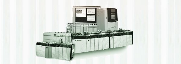
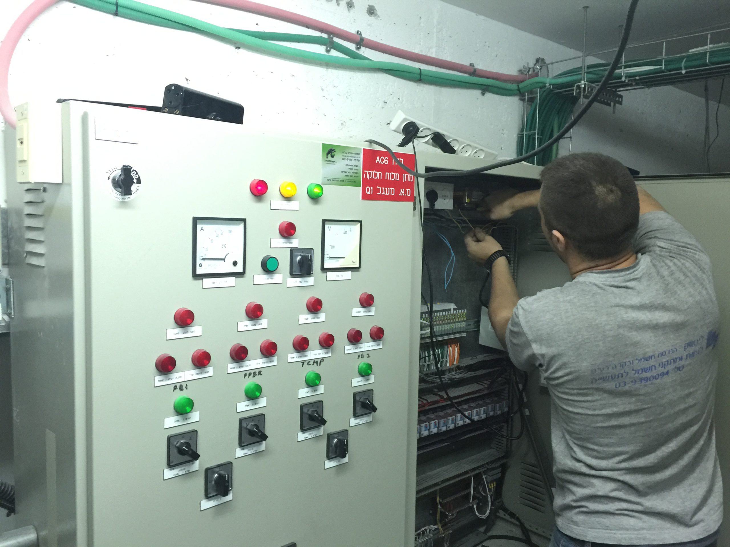
סמארטלוג'יק מתמחה בתכנון תהליך בתקן S-88 מאפיון  Control-Modules דרך Equipment modules וכלה בפאזות תהליכיות. שירותי החברה מסתמכים על ידע וניסיון רב בעבודה עם מערכות מים, RO ,CIP, מזקקות, מערכות HVAC ,Utilities, ומודולים מוכנים סטנדרט S-88 שפיתחנו עבור מערכות אלו.

הגדרת ISA

 International Society of Automation – ISA הינה אגודה טכנית ללא מטרות רווח, מיועדת למהנדסים, טכנאים, אנשי עסקים, מחנכים וסטודנטים, שעובדים, לומדים או מעוניינים באוטומציה תעשייתית ועיסוקים מקושרים לנושא, כגון מכשור.

 ISA כוללת תחומים טכניים והנדסיים רבים, והינה אחת מהארגונים המובילים בעולם בקביעת סטנדרטים והדרכת אנשי מקצוע בתעשייה בנושא אוטומציה.

הגדרת ANSI

American National Standards Institute –  ANSI הינה ארגון פרטי ללא מטרות רווח שמפקח על פיתוח תקנים מוסכמים בהתנדבות, עבור מוצרים, שירותים, תהליכים, מערכות וכוח אדם בארה"ב. ארגון זה גם מתאם בין תקנים אמריקאים ובינלאומיים, כך שמוצרים אמריקאים יוכלו להיות משווקים בכל העולם.

ANSI מאשרת תקנים מפותחים ע"י נציגים של ארגונים, סוכנויות ממשלתיות, קבוצות צרכנים, חברות, וגופים אחרים. תקנים אלו מבטיחים שתכונות וביצועי המוצרים הם אחידים, שהציבור משתמש באותם הגדרות ומינוחים, ושהמוצרים נבדקים באותה צורה. ANSI גם מספקת אישורים לארגונים שמסמיכים מוצרים או כוח אדם בהתאם לדרישות מוגדרות בתקנים בינלאומיים.

בקרת אצווה ANSI/ISA-88 – S-88

כללי

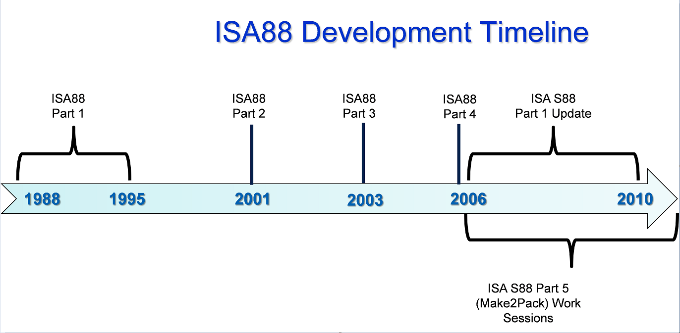
ועדת ANSI/ISA-88 פרסמה סדרת תקנים בנושא בקרת אצווה במערכות אוטומציה תעשייתיות.

תקן ,ANSI/ISA-88.00.01-2010, Batch Control Part 1: Models and Terminology מספק דגמים ומינוחים תקניים (סטנדרטיים) להגדרת דרישות בקרה עבור מפעלים שמייצרים אצוות.

תקן ANSI/ISA-88.00.02-2001, Batch Control Part 2: Data Structures and Guidelines for Languages,  מגדיר דגמים של נתונים(data)  שמתארים בקרת אצווה כפי שהיא משמשת במערכות אוטומציה תעשייתיות, מבני נתונים שמאפשרים קידום תקשורות פנימיות וגם בין יישומי בקרת אצווה שונים, והנחיות לגבי שפות שמייצגות מתכונים (recipes).

תקן ANSI/ISA-88.00.03-2003, Batch Control Part 3: General and Site Recipe Models and Representation,  מגדיר דגם עבור מתכונים כלליים ומקומיים; פעילויות שמתארות את שימוש המתכונים הכלליים והמקומיים במסגרת חברה אחת ובין חברות שונות; ייצוג מתכונים כלליים ומקומיים; ודגם נתוני מתכונים כלליים ומקומיים.

תקן ANSI/ISA-88.00.04-2006, Batch Control Part 4: Batch Production Records,  מספק הגדרה מפורטת עבור רישומי ייצור אצוות, וקובע דגם ייחוס לפיתוח אפליקציות לאחסנת ו/או המרת רישומי ייצור אצוות. יישומים מבוססים על תקן זה מאפשרים אחזור, ניתוח ודיווח של רישומי ייצור אצוות נבחרים.

ייעוד והיקף S-88

S-88 מיועד לאספקת תקנים והרגלי עבודה מומלצים לתכנון והגדרת מערכות בקרת אצווה בתעשיות עם בקרת תהליכים.

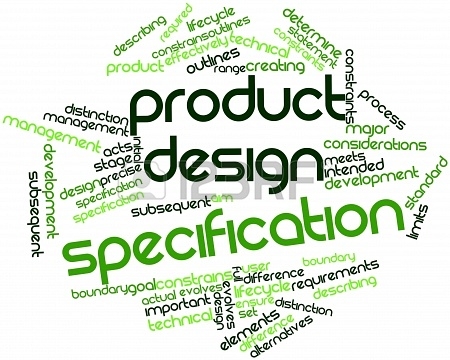
S88 מספק הנחיות לפיתוח וספציפיקציות של מערכות בקרת אצווה. הנחיות אלו גם מבוססות על תקנים והרגלי עבודה מומלצים ע"י ISA וארגונים אחרים, וגם משלים את התקנים וההמלצות הנ"ל. הנושאים שיילקחו בחשבון להכללתם ע"י הועדה הם:

  • הגדרת מונחים ספציפיים למערכות בקרת אצווה, שתעודד הבנה בין יצרנים ומשתמשים.
  • הגדרת שפה סטנדרטית למבנה נתונים של בקרת אצווה, שתקל על תכנות, על פעילויות קונפיגורציה, ועל תקשורת בין הרכיבים השונים של המערכת.
  • הגדרת מבנה נתונים סטנדרטי  למערכות אצווה, שיקל על פעילויות תקשורת הנתונים במסגרת אדריכלות המערכת.
  • קביעת אדריכלות בקרת אצווה סטנדרטית שמגדירה את הדגמים הפיזי ופונקציונאלי. הדגם הפיזי הוא המבנה ההיררכי שמקשר בין ציוד הבקרה לבין תקשורות הנתונים הנחוצות לאזורים הפיזיים המעורבים בבקרת האצווה. הדגם הפונקציונאלי מציג את הקישורים בין חמשת סוגי הבקרה: ניהול המתכונים, לו"ז, בקרה סדרתית(sequential) , בקרה תקנית (regulatory), מערכות חיגור (interlock)
  • לבטיחות.

סמארטלוג'יק מבצעת פרויקטי אוטומציה ובקרה מודולארית למתקני יצור תוך שימוש בתקן S-88

אוטומציה ובקרה – תזמון הרצת סקריפטים בסימפליסיטי

אוטומציה ובקרה – Configure new WW intoch installation

-אוטומציה ובקרה – איך גורמים ל HMI לעבוד עם הרשאות ווינדוס

אוטומציה ובקרה – PLCs Topic – Part 2

 אוטומציה ובקרה – PLCs Topic – Part 2

This articular is the third part of our  review about PLCs. After PLCs Functionality&Features and PLCs Topic – part 1 that covers the subjects of  Scan Time, System Scale, User interface & Communications, this part is about PLCs Programming, Digital and Analog Signals & PLC Advantages.

PLC– Programming

PLC programs are typically written in a special application on a PC, then downloaded by a direct-connection cable or over a network to the PLC. The program is stored in the PLC either in battery-backed-up RAM or some other non-volatile flash memory.

IEC 61131-3 defines several programming languages for programmable control systems, which emphasize logical organization of operations.

While the fundamental concepts of PLC programming are common to all manufacturers, differences in I/O addressing, memory organization and instruction sets mean that PLC programs are never perfectly interchangeable between different makers. Even within the same product line of a single manufacturer, different models may not be directly compatible.

PLC – Digital and Analog Signals

Digital or discrete signals behave as binary switches, yielding simply an On or Off signal (1 or 0, True or False, respectively). Push buttons, limit switches, and photoelectric sensors are examples of devices providing a discrete signal. Discrete signals are sent using either voltage or current, where a specific range is designated as On and another as Off. For example, a PLC might use 24 V DC I/O, with values above 22 V DC representing On, values below 2VDC representing Off, and intermediate values undefined. Analog signals are like volume controls, with a range of values between zero and full-scale. These are typically interpreted as integer values (counts) by the PLC, with various ranges of accuracy depending on the device and the number of bits available to store the data. Pressure, temperature, flow, and weight are often represented by analog signals. Analog signals can use voltage or with a magnitude proportional to the value of the process signal. Current inputs are less sensitive to electrical noise (i.e. from welders or electric motor starts) than voltage inputs.

PLC Advantages Relative to Other Control Systems

PLCs are well adapted to a range of automation tasks. These are typically industrial processes in manufacturing where the cost of developing and maintaining the automation system is high relative to the total cost of the automation, and where changes to the system would be expected during its operational life. PLCs contain input and output devices compatible with industrial pilot devices and controls; little electrical design is required, and the design problem centers on expressing the desired sequence of operations. PLC applications are typically highly customized systems, so the cost of a packaged PLC is low compared to the cost of a specific custom-built controller design.

Here are some examples of the PLCs used by smartlogic: 6XV1830-0EH10, 6ES7131-4BF00-0AA0,6ES7193-4CA40-0AA0,6ES7134-4GD00-0AB0,6ES7193-4CA40-0AA0, 6ES7138-4CA01-0AA0,6ES7193-4CC20-0AA0, 6ES7590-1AB60-0AA0, 6ES7511-1AK00-0AB0, 6ES7954-8LP01-0AA0,6ES7155-6AU00-0BN0

אוטומציה ובקרה – PLC Topics – Part 1

אוטומציה ובקרה – PLC Topics – Part 1

 PLC – Scan Time

A PLC program is generally executed repeatedly as long as the controlled system is running. The status of physical input points is copied to an area of memory accessible to the processor, sometimes called the "I/O Image Table". The program is then run from its first instruction rung down to the last rung. It takes some time for the processor of the PLC to evaluate all the rungs and update the I/O image table with the status of outputs. This scan time may be a few milliseconds for a small program or on a fast PLC.

PLC – System Scale

A small PLC has a fixed number of connections built in for inputs and outputs. Typically, expansions are available if the base model has insufficient I/O.

Modular PLCs have a chassis (also called a rack) into which are placed modules with different functions. The processor and selection of I/O modules are customized for the particular application. Several racks can be administered by a single processor, and may have thousands of inputs and outputs. A special high speed serial I/O link is used so that racks can be distributed away from the processor, reducing the wiring costs for large plants.

PLC- User interface

PLCs may need to interact with people for the purpose of configuration, alarm reporting or everyday control. Human-machine interface (HMI) is employed for this purpose. HMIs are also referred to as man-machine interfaces (MMIs) and graphical user interface (GUIs). A simple system may use buttons and lights to interact with the user. Text displays are available as well as graphical touch screens. More complex systems use programming and monitoring SW installed on a computer, with the PLC connected via a communication interface.

PLC- Communications

PLCs have built-in communications ports and corresponding communications protocols, such as RS-232, EIA-485, Ethernet, Modbus, BACnet or DF1.

Most PLCs can communicate over a network to some other system, such as a computer running a SCADA (Supervisory Control And Data Acquisition) system or web browser.

PLCs used in larger I/O systems may have peer-to-peer (P2P) communication between processors. This allows separate parts of a complex process to have individual control while allowing the subsystems to co-ordinate over the communication link.

Here are some examples of the PLCs used by smartlogic: 6XV1830-0EH10, 6ES7131-4BF00-0AA0,6ES7193-4CA40-0AA0,6ES7134-4GD00-0AB0,6ES7193-4CA40-0AA0, 6ES7138-4CA01-0AA0,6ES7193-4CC20-0AA0, 6ES7590-1AB60-0AA0, 6ES7511-1AK00-0AB0, 6ES7954-8LP01-0AA0,6ES7155-6AU00-0BN0

אוטומציה ובקרה – PLC – Programmable Logic Controller

אוטומציה ובקרה – PLC – Programmable Logic Controller

A Programmable Logic Controller – PLC is a digital computer used for automation of electromechanical processes, such as control of machinery on factory assembly lines. Unlike general-purpose computers, the PLC is designed for multiple inputs and output arrangements, extended temperature ranges, immunity to electrical noise, and resistance to vibration and impact. Programs to control machine operation are typically stored in battery-backed-up or non-volatile memory. A PLC is an example of a hard real time system since output results must be produced in response to input conditions within a limited time, otherwise unintended operation will result.

PLCs are usually programmed using application software (SW) on personal computers (PCs). The PC is connected to the PLC through Ethernet, RS-232, RS-485 or RS-422 cabling. Most PLCs used by smartlogic when designing an automation and control systems are the Siemens PLC and Allen Bradley's.The programming SW allows entry and editing of the ladder-style logic. Generally the SW provides functions for debugging and troubleshooting the PLC software, for example, by highlighting portions of the logic to show current status during operation or via simulation. The SW will upload and download the PLC program, for backup and restoration purposes.

PLC Functionality

The functionality of the PLC includes sequential relay control, motion control, process control, distributed control systems and networking. The data handling, storage, processing power and communication capabilities of some modern PLCs are approximately equivalent to desktop computers.

PLC Features

The PLC unit consists of separate elements, such as power supply, controller, relay units for in- and output

The main difference from other computers is that PLCs are armored for severe conditions (such as dust, moisture, heat, cold) and have the facility for extensive input/output (I/O) arrangements. These connect the PLC to sensors and actuators. PLCs read limit switches, analog process variables (such as temperature and pressure), and the positions of complex positioning systems. On the actuator side, PLCs operate electric motors, pneumatic or hydraulic cylinders, magnetic relays, solenoids, or analog outputs. The input/output arrangements may be built into a simple PLC, or the PLC may have external I/O modules attached to a computer network that plugs into the PLC.

 Here are some examples of the PLCs used by Smartlogic: 6XV1830-0EH10, 6ES7131-4BF00-0AA0, 6ES7193-4CA40-0AA0, 6ES7134-4GD00-0AB0, 6ES7193-4CA40-0AA0, 6ES7138-4CA01-0AA0, 6ES7193-4CC20-0AA0, 6ES7590-1AB60-0AA0, 6ES7511-1AK00-0AB0, 6ES7954-8LP01-0AA0, 6ES7155-6AU00-0BN0, 1746-NO4V, 1769-L16ER-BB1B

אוטומציה ובקרה- מהי מערכת בקרה תעשייתית?

אוטומציה ובקרה – Industrial Control System – ICS  – מערכת בקרה תעשייתיות

מערכת בקרה תעשייתית היא מונח כללי שמתייחס לסוגים שונים של מערכות בקרה שמשמשים בייצור תעשייתי, כולל: מערכת בקרה לפיקוח והשגת מידע -Supervisory Control and Data Acquisition – SCADA, מערכת בקרה  מבוזרת – DCS – Distributed Control System – , וקונפיגורציות של מערכות בקרה קטנות יותר כגון בקרים עם לוגיקה שניתנת לתכנות – Programmable Logic Controllers -PLCs שנמצאים לעתים קרובות במערכים תעשייתיים ותשתיות קריטיות.

.מערכות בקרה תעשייתיות משמשות בד"כ בתעשיות שמייצרות או מספקות מוצרים חשמליים, מים, נפט, גז, ומידע. סמארטלוג'יק מתמחה באוטומציה ובקרה, בתכנון,התקנה ותחזוק מערכות אלו

מערכת בקרה תעשייתיות לפיקוח והשגת מידע

Supervisory Control and Data Acquisition – SCADA – System

מערכת בקרה מסוג זה פועלת עם אותות מקודדים שעוברים דרך ערוצי תקשורת לאספקת בקרה על ציוד מרוחק (בד"כ ערוץ תקשורת אחד עבור תחנה מרוחקת אחת). מערכת הבקרה יכולה להשתלב עם מערכת להשגת מידע ע"י הוספת שימוש באותות מקודדות על ערוצי תקשורת, להשגת מידע על הסטאטוס של  הציוד המרוחק לצורך תצוגה או הקלטה.

מערכות בקרה אלו מבוססות על מערכות ממוחשבות שמנטרות ומבקרות תהליכים  תעשייתיים. מערכות מסוג SCADA נבדלות היסטורית ממערכות תעשייתיות אחרות עקב תהליכים בקנה-מידה גדולים שכוללים אתרים רבים מפוזרים במרחקים גדולים.

מערכת בקרה תעשייתיות מבוזרת

Distributed Control System- DCS

מערכת בקרה מסוג זה משמשת  לבקרת תהליכים  תעשייתיים כגון ייצור חשמל, זיקוק נפט וגז, אספקת מי שתייה וטיפול במי ביוב, וייצור מוצרים כימיים,  מוצרי אוכל ומכוניות. מערכות מסוג DCS משתלבות במערכי בקרה הכוללים פיקוח על תת-מערכות משולבות אחראיות על בקרת ציוד בתהליכים מקומיים.

בקרת מוצרים ותהליכים מושגת בד"כ בעזרת חוגי בקרה עם הזנה אחורה – feed-back control loop – או הזנה קדימה – feed-forward control loop, כך שתנאי המוצר או התהליך נשמרות באופן אוטומטי תוך טווח מוגדר סביב ערך נתון (set point). השגת תנאי מוצר או תהליך במסגרת טווחים מוגדרים אפשרית רק בעזרת בקרים מסוימים הניתנים לתכנות.

בקר עם לוגיקה שניתנת לתכנות – PLCs

בקר מסוג זה מספק בקרה של פעולות לוגיות בוליאניות (Boolean), קוצבי זמן, ותהליכים רציפים (בדגמים מסוימים). יחסי ההגדלה הפרופורציוניים, אינטגרליים ו/או דיפרנציאליים של הבקר בתהליכים רציפים ניתנים לכוונון כדי להשיג את דיוק הטווח מוגדר וכן את מהירות התיקון העצמי במקרה של תקלות בתהליכים. בקרים מסוג PLC  משמשים בהרחבה בתעשיות מבוססות על תהליכים. בקרים אלו  מתבססים על מחשבים שמבקרים ציוד ותהליכים תעשייתיים. אם כי בקרים מסוג PLC  מסוגלים לבקר מרכיבי מערכת שפועלים בעזרת מערכות מסוג SCADA ו- DCS, הם גם באופן תדיר משמשים כרכיבים עיקריים בקונפיגורציות של מערכות בקרה קטנות יותר. הם משמשים גם להענקת בקרה רגולטורית של תהליכים דיסקרטיים , כגון קווי הרכבת מכוניות, ובנוסף משמשים בכמעט כל תהליכי הייצור התעשייתיים.

ולידציה – Design Specification – DS

ולידציה – Design Specification – DS

The Design Specification -DS is part of the validation documentation that provides information necessary to complete the design of the project. This document covers only the DCS side and integration with ELT-GHS-150-T3 Gas Heater skid

DS Content

The DS is usually structured in a relatively standard fashion, with predetermined chapters and sections, where the final contents are tailored according to the type and size of the system under validation.

:The main chapters and sections of this DS are

Hardware Specification

Wiring and Electrical Cabinet Drawing

Communication and Network Design

Other Documentation

ProfiBus Monitoring Values List

Running Logic

Alarms List

Alarm Response

Disaster Recovery

Programming Design

Appendixes

Hardware Specification

.This section defines the required I/O allocation, according to the wiring diagram document No. P09204-020 Rev2, and 35800SIS0-N0

8 digital inputs

1 digital outputs

ProfiBus connection

Wiring and Electrical Cabinet Drawing

:This section lists the following design information

New Electrical drawing is not needed

:All I/O should be named in a standard fashion, i.e., XXXX-YYY-ZZZ, where

XXXX – 4 prefix letters which indicates the containing system; in this case, the system is PRMS

.YYY – indicates the instrument type according to Siemens naming standard – document no

ZZZ – indicates the serial continuing number

.Siemens Engineering file update is needed in Chapters18C 18D 18E. Other chapters should be examine and discussed in the FRS

.BOP PLC must be stopped during the wiring and ProfiBus module installation. Dalkia should be supply with time table

Communication and Network Design

:This section lists the following design information

.The communication used in this project is Profibus

.The Profibus communication protocol and wiring design will be provided by Siemens

.Siemens Engineering file update is needed. All communication and network chapters should be updated

Communication and Network Design

Siemens Engineering file "stand alone skids and instruments" chapter should be update; all Heater manuals and instructions should be attached to this chapter.

ProfiBus Monitoring Values List

tSP Target Setpoint – Setpoint differential CT15/14 – CT15/13

All  Operator.MAIN items – To be later configured

All Operator. SYSTEM.StatusWords.Output) – To be later configured

Man Manual/Auto Mode 76 AUTO (0) – +VFD manual percents

Running Logic

start conditions

Heater valve V101 is open. – GS101 HEATER INDICATION.

Heater valve position V102 is open.

Heater bypass valve V103 is closed.

DCS 10EKA01CF001>1500m3h (indicating that at list one of the gas turbines is on).

DCS 25Barg<10EKA001CP001<45Barg (Gas pressure operation range).

All Heater trips are acknowledged and cleared.

Operator pressed "Start" from DCS.

Alarms List

All alarms from profibus

Alarm Response

Holding/Restart Logic

No alarm response from the DCS.

Disaster Recovery

Perform stop operations as in paragraph

  1. Power shut down
  2. Compressed air supply shut down

 Programming Design

AS (Automation system – PLC) that will be programmed in this integration will be BOP.

The synoptic screen will be programmed and be added to the PRMS screen, as described in Appendix 1 – Synoptic Screen.

All instruments, EG valves and transmitters, will be created according to Siemens standards.

All instruments will be set to READ ONLY, except the START and STOP buttons.

Appendixes

The DS appendixes present examples of design drawings.

Appendix 1 – Synoptic Programming Design.

Appendix 2 – Chapter 18E BOP Example of Electrical Drawing (to be updated)

Appendix 3 – Example of Network Drawing (to be updated)


הוראות חיבור ממיר 485 USB עם ModScan

אוטומציה ובקרה – הוראות חיבור ממיר 485USB עם ModScan

מומחי סמארטלוג'יק מעבירים הדרכות באופן קבוע בנושאי אוטומציה ובקרה הפעם מומחה סמארטלוג'יק מסביר בפירוט כיצד יש לבצע חיבור של ממיר 485USB עם ModScan

פעל כדלקמן כדי לחבר ממיר 485USB עם ModScan, תוך התייחסות לשלבים במלל וצילומי המסכים בהמשך לכל שלב:

  1. הוראות חיבור ממירבשלב ראשון, חבר מתאם 485 ל- USB. המסך לעיל מראה את מיקומו של הפורט הסריאלי 485 בחלון "Device Manager".
  2. התקן דרייבר שהאפליקציה מצאה לבד ב- Widows Update ע"י לחיצה על כפתור "Finish" בחלון "Found New Hardware Wizard" (מסך ראשון בהמשך) , בהמשך ע"י לחיצה על כפתור "Next " באותו חלון הכולל בחירה בהתקנה אוטומטית של התוכנה (מסך שני), ואחר כך על ידי לחיצה על כפתור "Finish" בחלון להשלמת ההתקנה (מסך שלישי).הוראות חיבור ממיר 2
    מסך 2 סעיף 2 בהוראות ממירהוראות חיבור ממיר 4


  1. בחר את "USB Serial Port (COM3)" בחלון "Device Manager", כפי שמראה המסך הראשון בהמשך. וודא שההגדרות של הפורט נכונות בחלון " SB Serial Port (COM3) Properties" (מסך שני) ולחץ על הכפתור "Cancel".הוראות ממיר 5

המסך ה2 בסעיף 3 הוראות ממיר


  1. פתח את תוכנת ModScan על ידי לחיצה על כפתור ההפניה " "ModScan32במסך ""Windows ופתיחת חלון "ModScan32 – ModSca1". בחלון זה בחר "Connection" ¬ "Connect" (מסך ראשון בהמשך) לפתיחת חלון פנימי "Connection Details" (מסך שני). בחלון זה בחר "Direct Connection to COM3". בהמשך בדוק את פרטי החיבור, שנה את ההגדרה בשדה "Parity" ל- NONE"" (מסך שלישי), ולחץ על הכפתור "OK".מסך 1 סעיף 4 הוראות ממיר
    מסך 2 סעיף 4 הוראות ממיר
    מסך 3 סעיף 4 הוראות ממיר

  2. המשך עם חלון "ModScan32 – ModSca1" (מסך ראשון בהמשך). בחר "03: HOLDING REGISTER" בשדה "MODBUS Point", "5" בשדה "Length", "5" בשדה "Device Id" (שמגדיר את המכשיר אליו צריכים להתחבר). אם מספר המכשיר בשדה "Device Id" נכון, והמכשיר מחובר למתאם 485 כדרוש [קצה (+) ל- (+), וקצה (-) ל- (-)], ההודעה "MODBUS Message TIME-OUT" באדום תיעלם, המספר בשורה "Valid Slave Responses" במסגרת "Reset Ctrs" יהיה גדול מ- "0", והערכים של הפרמטרים 40005 – 40001 יהיו אפסים או מספרים אחרים. מסך אחרון הוראות ממיר

להדרכה בנושא העלאת תוכנה מבקר סימנס לחץ כאן, להדרכה בנושא תזמון הרצת סקריפטים בסימפליסיטי לחץ כאן,  להדרכה בנושא Configure new WW intoch installation לחץ כאן  להדרכה בנושא איך  גורמים ל HMI לעבוד עם הרשאות ווינדוס לחץ כאן לתשובות בנושאים נוספים בתחום האוטומציה והבקרה או ולידציה מוזמן ליצור איתנו קשר