Smartlogic

OEE (Overall Equipment Effectiveness) מדד משולב לניתוח יעילות הייצור

במסגרת ניסיוננו הרב בהטמעת מערכות OEE, רצינו לעשות קצת סדר בהבנת המונח OEE ואיך הוא עוזר לארגון.

OEE הגדרה

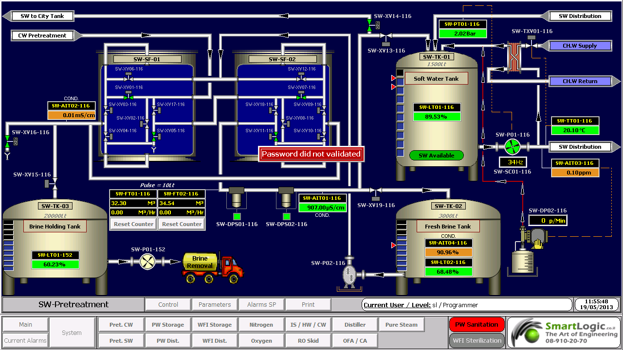
OEE  הוא מדד משולב לניתוח יעילות תהליך הייצור, כמו כן הוא מדד אוניברסאלי מקובל למדידת היעילות הכוללת של הציוד.
ה-OEE  (מדד משולב לניתוח יעילות תהליך הייצור) לוקח בחשבון מגוון של רכיבי משנה בתהליך הייצור וביניהם זמינות, ביצוע ואיכות, לאחר שגורמים שונים נלקחים בחשבון התוצאה מתבטאת באחוזים. אנו יכולים לצפות באחוזים אלה כתמונת מצב נוכחית ליעילות הייצור למכונה, קו ייצור או תא.
OEE (מדד משולב לניתוח יעילות תהליך הייצור) =   זמינות *ביצוע * איכות


תהליך ייצורו של מוצר הוא תהליך מורכב. ללא מדדים וללא קווי יסוד ניתן לאבד שליטה בקלות, ולא אתה תנהל את העסק אלא הייצור ישתלט.

OEE  הוא כלי שמשלב  נושאים ונתוני ייצור מרובים על מנת לספק מידע על התהליך. על ידי ניתוח וחישוב נתונים הוא מתפקד גם כמסגרת לניתוח שורש הבעיה.

באמצעות תהליך מתועד של שילוב נתוני יסוד, ה- OEE מספק מידע / תהליך מסוים. כל חברי צוות הייצור, החל מטכנאי הרכבת ועד לאנשי הכספים יכולים להשתמש בנתונים אלו כדי להבין את המצב הנוכחי של התהליך שמתרחש ברצפת ייצור. ועל ידי אי זמינות  המכונה תיווצר השפעה שלילית במסגרת הנתונה : ביצוע זמינות ואיכות. המדד מספק מסגרת כדי שנוכל לעקוב אחר בעיות יסוד ואת הסיבות לבעיות.

המדד מספק גם מסגרת שיפורים בתהליך הייצור. ישנם שישה גורמים שליליים המשפיעים על מסגרת ה-  OEE  ובמסגרת מעקב אחר המדד ניתן לשפר את התהליך והמרכיבים הם:


  • OEE (מדד משולב לניתוח יעילות תהליך הייצור).
  • זמינות
  • ביצוע
  • איכות

ה-OEE  (מדד משולב לניתוח יעילות תהליך הייצור) – הוא מדד פשוט ומיידי שבא להצביע על המצב הנוכחי של תהליך ייצור. כמו כן משמש גם ככלי מורכב המאפשר להבין את ההשפעה של הבעיות השונות בתהליך הייצור וכיצד הן משפיעות על התהליך כולו.

OEE  (מדד משולב לניתוח יעילות תהליך הייצור) = זמינות*ביצוע*איכות

זמינות – הזמינות מתייחסת לזמינות המכונה או התא בשעת הייצור ברמת התכנון. ברמה הבסיסית ביותר כאשר התהליך בפועל הוא יצירת ערך עבור המשתמש הסופי. כאשר התהליך נעצר הוא גורם ליצירת עלות מיותרת בין אם זה בשל כשל מכני, חומרי גלם או בעיות מפעיל התא או המכונה גם בייצור או באי ייצור.  על ידי השוואת זמן ריצה מתוכנן לזמן ריצה בפועל, המרכיב הזמין של OEE  מאפשר קביעת של תוצר שאבד בשל השבתה.


הביצועים – הביצועים נקבעים על ידי כמות הבזבוז שנגרם עקב  ניצול לא אופטימלי של המערכת. היא נבדקת על ידי השוואת זמני מחזור בפועל לעומת זמני מחזור אידיאליים. המדד מאפשר קביעה של תוצר שנפסל בידי מחזורים הפועלים ושלא עמדו בנורמה.


איכות – האיכות מתמקדת בזיהוי הזמן שבוזבז על ידי ייצור מוצר שאינו עומד בתקני האיכות. על ידי השוואת כמות התוצרים שיוצרו לעומת אחוז התוצרים שנפסלו.


OEE שימושים בחברות וארגונים

כשלעצמו המדד  מספק נתונים על תהליך הייצור בלבד. חברות המשתמשות ב – OEE כמדד ראו הצלחה כאשר שלבו אותו עם תוכניות ייצור רזה בכלל וגם כחלק ממערכות TPM  (שיפור מתמשך של ביצועי הציוד בארגון). בעת שימוש עם OEE בשילוב מערכות אלו היתרונות הופכים למשמעותיים:


  • קשר ישיר בין יעילות הייצור לדוחות כספיים.
  • קיצור זמן אבחון תהליכים.
  • קיצור זמן ROI (החזר השקעה) על ידי ניצולת מירבית.
  • הקטנת עלויות על ידי ניצול אופטימלי של החומר.
  • שיפור שביעות רצון הלקוחות על די שיפור איכות המוצר.


לפגישת ייעוץ, אנא התקשר אלינו 08-9102070

ממשק אדם-מכונה HMI – אוטומציה ובקרה

מה זה HMI?

ממשק אדם-מכונה Human-Machine Interface – HMI מתרחש בתחום בו חלה אינטראקציה בן בני אדם ומכונות. מטרת האינטראקציה היא אפשרות  לניטור ובקרה יעילים של  אותן מכונות ע"י מפעיליהן, כאשר המכונות מספקות מידע בהיזון חוזר שמאפשר למפעילים לקחת החלטות נכונות בזמן התהליך. לממשק זה יש שימוש נרחב בעיצוב, יצור ובקרה על ציוד תעשייתי, ועל ניטור ובקרה על תהליכים תעשייתיים.

עם השימוש הגדל במחשבים אישיים ובקרים ממוחשביםProgrammable Logic Controller – PLC, הפך HMI למונח  המתייחס לרוב לייצוג הגרפי של הציוד והתהליכים התעשייתיים על פני מסכי המחשבים.

סמארטלוג'יק משתמשת ב -PLCs מתוצרת סימנס (Siemens) ואלן ברדלי (Allen Bradley)  לדוגמא :

6XV1830-0EH10, 6ES7131-4BF00-0AA0,6ES7193-4CA40-0AA0,6ES7134-4GD00-0AB0,6ES7193-4CA40-0AA0, 6ES7138-4CA01-0AA0,6ES7193-4CC20-0AA0, 6ES7590-1AB60-0AA0, 6ES7511-1AK00-0AB0, 6ES7954-8LP01-0AA0,6ES7155-6AU00-0BN0

מונח אחר, פחות שימושי הוא ממשק איש-מכונה הוא  Man-Machine Interface – HMI. מונח זה היה נפוץ אך זכה להתרעמות מצד ארגוני הנשים שדיברו על כך שגם נשים הם משתמשות בממשקים אלו ומהוות חלק מהם כך שונה השם למונח הכללי אדם או באנגלית Human.

HMI מערב ציוד (חומרה) היקפי, ורכיבי תוכנה, כגון ממשקים גרפיים.

בתחום המקושר ל- HMI, שנקרא Human-Computer Interaction – HCI, חוקרים את הייצוב והשימוש בטכנולוגיית המחשב, תוך מיקוד מיוחד בממשקים בין אנשים ומחשבים. החוקרים בתחום זה מתבוננים בצורות שבהם אנשים פועלים מול מחשבים, ומעצבים טכנולוגיות  שמאפשרות אינטראקציה  בין אנשים ומחשבים באופנים חדשים.

אנשים  פועלים מול מחשבים בצורות שונות, והממשק בו משתמשים משחק תפקיד מכריע בהקלה באינטראקציה. אפליקציות במחשב שולחני, דפדפן (browser) אינטרנטי,  מחשבים נישאים, וכו', משתמשות בממשק לשימוש גרפי Graphical User Interface – GUI באופן הנפוץ ביותר; ממשק לשימוש קולי Voice User Interface – VUI, פחות נפוץ, משמש לזיהוי דיבור ומערכות סינתוז synthesizing. השימוש ב- multi-modal GUI מאפשר להשתלב עם גורמים מסוימים שלא ניתנים  לתקשורת עם כלי ממשק אחרים.

שימוש ב-HMI לצורכי בקרה ואוטומציה

בתחום הבקרה והאוטומציה אנו עוסקים רבות בממשק Human-Machine Interface – HMI בעת תכנון ותפעול מערכות בקרה תעשייתיות.

תכנון וביצוע פרויקטים הנדסיים בתחום הבקרה האוטומציה היא המומחיות של סמארטלוג'יק, בקרה מפעלית ובקרות תהליך, בקרות מבנה BMS.  שיטות עבודה שלנו מאפשרות ביצוע אינטגרציה במהירות שיא, בין פרויקט חדש ומערכות המפעל הקיימות. סמארטלוג'יק מבצעת פרויקטי אוטומציה ובקרה מודולארית למתקני יצור תוך שימוש בתקן S-88.  סמארטלוג'יק היא גם  נציגה בלעדית של Siemens בארץ לתמיכה במערכת PCS7 ועובדת על בסיס קבוע, עם מרכז התמיכה העולמי בגרמניה באמצעות מערכת בקרת איכות מחמירה העומדת בתקן ISO9000.

להדרכה איך גורמים ל HMI לעבוד עם הרשאות ווינדוס לחצו כאן.

ולידציה – Operation Qualification – OQ- part 2

ולידציה – Operation Qualification – OQ- part 2

Protocol Preparation Overview

This article provide overviews of the main test procedures and verification, and their purposes. This OQ procedure is generic, and relevance of the test procedures and verifications provided below depends on the composition of the system under validation

:Note

As mentioned in the previous artcle on OQ Protocol Contents, the final contents of the OQ protocol are tailored according to the type and size of the system under validation. Since this document is generic, it covers test procedures that may not be necessary in small or simple systems

:Where relevant, the OQ procedure may consists of five main test procedures

HMI Screen Test Procedure – intended to verify that the HMI screens provide the graphic design and functionality required for properly monitoring and controlling the environmental conditions in the user's

Parameters Lists Verification – intended to verify that the system parameters lists comply with the values specified in the SSO

Two types of parameters are checked

Process parameters

Alarm parameters

System Operation Test Procedure – intended to verify that system monitoring and control components are capable of maintaining the user's facility within specified temperature, humidity and pressure levels

System Alarms Test Procedure – intended to verify that when the specified temperature, humidity and pressure levels exceed its specified limits, an alarm message is displayed, and an SMS or e-mail notification is sent to relevant personnel

Test of HMI Compliance with 21 CFR Part 11 – This test is intended to verify that the HMI meets Valtech Cardio's URS regarding 21 CFR Part 11. These : requirements are divided into 5 categories for the sake of clarity

Security

Electronic Records

Audit Trail

Archive

Backup

 HMI Screen Test Procedure

This section includes specific test procedures for all the relevant HMI screens, where each test procedure serves to verify that the specific HMI screen provides the graphic design and functionality required for its intended purpose within the monitoring and controlling functions

Parameters Lists Verification

:This procedure covers the verifications of two types of parameters

Process parameters

Alarm parameters

Process Parameters List Verification

This procedure is intended to verify that:

The system enables to set the default values of the process set-points of each monitored environmental parameter.

The system provides automatically the corresponding low and high limits of these default values. These limit values are listed in  below

The system rejects all the SP values that exceed their allowed ranges, as specified in the SSO

Alarm Parameters List Verification

:This procedure is intended to verify that

The system enables to set the default values of the alarm set-points of each monitored environmental parameter

The system provides automatically the corresponding low and high limits of these default values

The system rejects all the SP values that exceed their allowed ranges, as specified in the SSO

 System Operation Test Procedure

This procedure is intended to verify that system monitoring and control components are capable of maintaining the user's facility within specified temperature, humidity and pressure levels. For this purpose, it is necessary to temporarily change set-points, in order to activate the control devices

System Alarms Test Procedures

This procedure is intended to verify that, when an environmental parameter value exceeds the specified normal range, the system reacts as specified in the SSO, by providing a specified alarm indication, a relevant e-mail alarm message, and relevant records in the Current Alarms and Historical Alarms screens

Test of HMI Compliance with 21 CFR Part 11

This test is intended to verify that the HMI meets the user's URS regarding 21 CFR Part 11. These requirements are divided into 5 categories for the sake of :clarity

Security

Electronic Records

Audit Trail

Archive

Backup


ולידציה – Operation Qualification – OQ- part 1

ולידציה – Operation Qualification – OQ- part 1

Protocol Preparation Overview

The Operation Qualification (OQ) protocol is part of the validation documentation that covers the verification of the proper operation of the system under validation in the user's facility. This OQ protocol is generic, and the system may include a PC with Human/Machine Interface (HMI), a Programmable Logic Controller* (PLC), pressure, temperature and humidity transmitters, and other monitoring and control components designed to maintain the user's facility in proper environmental conditions (temperature, pressure and humidity)

This OQ protocol is intended to verify that the system under validation operates according to the acceptance criteria specified in the Schedule of System Operation (SSO), and also meets the vendor's requirements and the user's specifications. It must be reviewed and approved prior to the OQ performance

OQ Protocol Contents

The OQ protocol is structured in a relatively standard fashion, with predetermined chapters and sections, where the final contents are tailored according to the type and size of the system under validation

:The chapters and sections of an OQ protocol are

Documents Verification – procedure intended to verify that all the documents required for performing the OQ procedure are approved and available

OQ Test Procedures – this is the main part of the protocol, and provides the description of the test procedures and the result tables for filling and approving the test results

: Note

As the final contents of the OQ protocol are tailored according to the type and size of the system under validation, and this document is generic, it covers test procedures that may not be necessary in small or simple systems

Documents Verification

:This procedure is intended to verify that all the documents required for performing the OQ procedure are approved and available. These documents are

Functional Requirements Specification (FRS)

Installation Qualification (IQ) Protocol

Piping and Instrumentation Drawing – P&ID

Input/Output (I/O) List

Schedule of System Operation (SSO)

OQ Test Procedures

This chapter contains all the test procedures or verification required to verify the system under validation is properly installed and can be properly operated according to the supplier's requirements and user's specifications

:Each test procedure or verification must include the same contents

Purpose or Objective

Procedure or Method

Acceptance Criteria

Test Results

*Here are some examples of the PLCs used by smartlogic: 6XV1830-0EH10, 6ES7131-4BF00-0AA0,6ES7193-4CA40-0AA0,6ES7134-4GD00-0AB0,6ES7193-4CA40-0AA0, 6ES7138-4CA01-0AA0,6ES7193-4CC20-0AA0, 6ES7590-1AB60-0AA0, 6ES7511-1AK00-0AB0, 6ES7954-8LP01-0AA0,6ES7155-6AU00-0BN0

ולידציה -Testing and HW/SW Type and Maturity

ולידציה -Testing and HW/SW Type and Maturity – GAMP

Process automation systems generally comprise several elements. Categorizing these elements according to those described in GAMP 4 can assist in targeting testing and validation effort.

Some functional elements may be fully contained within the system standard packages or firmware (FW), while others may require different degrees of configuration or customization. In general, the greater the degree of customization, the greater the scope of testing required.

For example, if an item of the process equipment is to be controlled, the User may have several options for implementing the process control system functional element.

:Typical Test Phases for Process Automation Systems

Complex control exists as single, mature 'equipment level' library module, where functions can be selected/ deselected and  setup parameters entered

For example, sterilizer module with selectable cycle types

Application Life Cycle Testing: selection of functions, setup parameters

:Typical Test Phases

FAT and /or

SAT

IQ/OQ/PQ of process equipment

Complex control built up from mature, interlinked 'device level' library modules, which must have correct parameters entered

For example, sterilizer control, built up from valve, motor, PID, set-point program modules.

Application Life Cycle Testing: selection and linking of modules functions to give correct functionality, setup parameters

:Typical Test Phases

FAT

SAT

IQ/OQ/PQ of process equipment

Complex control built up from application specific modules, themselves built up from low-level library modules, or from simple coded steps within a predefined structure.

For example, sterilizer control configured in ladder logic

Application Life Cycle Testing: functionality of custom coded modules, selection and linking of modules functions to give correct functionality, setup parameters

:Typical Test Phases

Module test

FAT

SAT

IQ/OQ/PQ of process equipment

Complex control custom added

For example, sterilizer control coded in C++

Application Life Cycle Testing: functionality of custom coded modules, interaction between custom coded modules, selection and linking of modules functions to give correct functionality,setup parameters.

:Typical Test Phases

Module test

Module integration test

FAT

SAT

IQ/OQ/PQ of process equipment

:Notes

The suggested test phases listed above are typical only; they may be increased or decreased to reflect the complexity of the application, and the impact on product quality, patient safety and data integrity

The above assumes mature, 'industry proven' library modules. If these are created specifically for the application, then they need to be treated as custom code

Smartlogic expertise in validation of current and new systems to meet the most rigid requirements of the FDA and CFR protocols.

ולידציה – GAMP – Test Example – part 2

Good Automated Manufacturing Practice (GAMP) – Test Example

Testing Process Automation Systems

This article cover  the second part of  our  Good Automated Manufacturing Practice (GAMP) test example. This part will cover  the typical test phases for supplier's application SW Module Testing, supplier's Module Integration Testing and the supplier's Integration Testing – cont'd

                     Typical Test Phases

 Typical test phases for a complex process automation system. This example assumes that the system is configured by a Supplier and delivered to site after a FAT. Test system can also be configured by the system integrator or by the User. In this case, the same coverage is required, but the test phasing and location may be different.

The User and Supplier should work together to develop an overall approach to testing that reflects the risk assessment output and ensures adequate test coverage of the functionality, whilst avoiding unnecessary repeated tests.

: Typical Test Phases for Process Automation Systems

 Supplier's Application SW Module Testing

Done at the Supplier's premises after the module has been placed under configuration control and code reviewed. Before system integration. Module testing generally covers: Module data handling

 Interfaces to other modules

 Operator interfaces

 Module functionality Failure paths and response to fault conditions should be included within the tests

Supplier's Module Integration Testing

Done at the Supplier's premises.After individual module have been tested and integrated into a single unit.Before full system integration

Module integration testing generally covers: Correct operation of Interfaces between modules

Failure paths and response to fault conditions should be included within the tests

Supplier's Integration Testing –

Done at the Supplier's premises.After module testing, and before the User is invited to witness the FAT

Integration testing generally covers:

 HW

I/O interfaces

Operator interfaces

Interfaces to other equipment

System functionality

Data handling functions

Failure paths and response to fault conditions should be included within the tests

:HW tests typically include

·      Checking system build against approved HW specifications and drawings

·      Recording system components, version numbers (including SW versions) and capacities

·      Checking electrical supplies and grounding

Supplier's Integration Testing (cont'd) –

Checking correct power up of system components

Checking any self test/diagnostic information

Checking correct communication on standard interfaces

:I/O interface tests typically include

Exercising inputs and outputs to check correct configuration of ranges, alarms, etc.

:Operator interface tests typically include

System displays and navigation

Security and access controls

:Tests for interfaces to other equipment typically include

Checks of communications protocol setup

Checks that the required data can be transferred

Checks of actions in case of communications failure

Tests for system functionality typically include:

Monitoring functions

Alarm strategies

Control functions)control modules, equipment modules, procedural control(

Power failure and recovery

Component failure and redundancy

Performance checks

:Tests for system data handling typically include

Operator data entry

Data formatting and quality checks

Checks of calculated values

Checks of recipes

Checks of access to current process data, alarms and events )displays, alarm summaries, etc.(

Checks of access to historical process data, alarms and events )trends, reports, alarm histories, etc.(

Checks of audit trail functionality

Checks of data capacity and retention times

Checks of archive and restore

Checks of provisions for electronic signatures

Checks of disaster recovery procedures

End of  ולידציה – GAMP – Test Example – part 2


ולידציה – GAMP – Test Example – part 1

Good Automated Manufacturing Practice (GAMP) – Test Example

Testing Process Automation Systems

This article cover  the first part of  our  Good Automated Manufacturing Practice (GAMP) test example.

                                     Definitions

This section provides brief descriptions of three different types of process control systems.

                  Configurable Equipment

Configurable Equipment is the collective name given to simple configurable instruments/ devices, such as 3-term controllers, check scales, bar code readers, etc. Their functionality depends on that their configuration setup meets the process requirements. The software (SW) components of these systems are typically defined as GAMP SW Category 2.

                    Embedded Systems

Embedded Systems is the collective name for systems with a greater degree of configuration and programmability. Devices such as Integrated Circuits (ICs) with configuration setups and Programmable Logic Controllers (PLCs), which are supplied as an integral part to an item of process equipment, e.g., PLCs controlling a centrifuge or packaging machine, or IC embedded in High Performance Liquid Chromatography (HPLC) systems. Embedded Systems typically contain SW components belonging to multiple GAMP categories.

                 Stand-Alone Systems

Stand-Alone Systems is the collective name for large programmable control systems having distributed functionality across a network, e.g., Distributed Control Systems (DCSs), and Supervisory Control and Data Acquisition (SCADA). They are engineered as an entity to control a complete plant. Stand-Alone Systems typically contain SW components belonging to multiple GAMP categories.

                      Testing and the GAMP Life Cycle 

     Stand-Alone Systems

A process automation system developed for a new application typically requires some or all of the following test phases:

Suppliers Module Testing

Suppliers Module Integration Testing

Suppliers Integration Testing

Factory Acceptance Test (FAT)

Site Acceptance Test (SAT)

Installation Qualification (IQ)

Operation Qualification (OQ)

Performance Qualification (PQ)

The exact combination of testing required for a particular system should reflect its complexity, the maturity of its underlying SW and hardware (HW) elements, and the risk impact on product quality, patient safety and data integrity. Collectively these will determine the risk priority. The phrase 'low risk' should be understood as 'having a low risk priority, as determined by a formal risk assessment'.

Testing of modifications, patches or upgrades should be related to the risk priority of the change. For example, it may be appropriate for parameter changes to be applied directly to the production environment, assuming that the system have been range checked for such parameter.

End of ולידציה – GAMP – Test Example – part 1

ולידציה – GAMP – Hardware & Software Test Environments

ולידציה –  GAMP – Hardware & Software  Test Environments

Good Automated Manufacturing Practice (GAMP) Hardware (HW) Environment Test

HW can be categorized according to both GAMP 4 HW category (standard or custom) and its function within the test environment. It can be one o f these three things

 Part of the system under test, i.e., part of the production HW

 Test HW representing part of the production environment, which may be needed because it is not feasible to include a certain element of the production system in the test environment

A separate test system, which may be used to represent an external system

          Representative Test Environment

As started previously, the HW environment should represent as close as possible the production environment

For example, if the test environment uses a standard network hub of the same type as the production environment, then the substitution probable introduces low probability if invalid test results in the production environment. If, however, the network cabling in the test environment is uses short patch cables, whilst the real environment has cable runs close to the maximum recommended length, there is clearly a possibility of different network behavior, and additional tests on site may be needed to prove proper network performance

                    Control of Test Environment

For standard HW (per GAMP 4 HW Category 1), the manufacturer's reference and serial numbers should be recorded.

For custom HW (per GAMP 4 HW Category 2), the version of the item and its controlling specification should also be recorded.

For all test HW, any applicable calibration status should be recorded in the context of the specific

                         Removal from Production Environment

If the test HW is added in the way that it may appear in the production environment, then, this should be documented a temporary modification to the production system. Removal of the temporary modification should be documented as well

Good Automated Manufacturing Practice (GAMP)  Software (SW) Environment Test

Test SW can also be categorized according to both GAMP 4 SW category and its function within the test environment:

Part of the system under test, i.e., part of the production HW

Test SW representing part of the production environment

A separate test system

              Representative Test Environment

The SW environment should represent as close as possible the production environment

For example, if the test environment uses a process controller of the same type as the production environment, then the substitution probable introduces low probability if invalid test results in the production environment. If, however, a particular interface is simulated in the test environment, a possibility remains that different timing factors or process dynamics could affect the operation in the production environment, and additional tests on the production interface may be appropriate

                        Control of Test Environment

For standard SW (per GAMP 4 SW Category 1, 2 or 3), the manufacturer's reference and version numbers (including installed patch cables) should be recorded. Any configuration or setup parameters should be controlled

For configured or custom SW (per GAMP 4 SW Category 4 or 5), the item should be placed under configuration management and the version in use recorded

              Removal from Production Environment

If the test SW is added in the way that it may appear in the production environment, then, this should be documented a temporary modification to the production system. Removal of the temporary modification should be documented as well

ולידציה –  GAMP – Hardware & Software  Test Environments

בקרה ואוטומציה ליט"אות -HVAC / AHU control

בקרה ואוטומציה ליט"אות -HVAC / AHU control

HVAC stands for Heating, Ventilating and Air Conditioning. AHU stands for Air Handling Unit.

HVAC and AHU control systems provide centralized monitoring and control of these systems, designed to maintain selected rooms in research and production facilities within specified pressure, temperature and humidity levels. This is achieved by operating and monitoring active components or actuators, and by monitoring environmental conditions, such as pressure, temperature and humidity, using corresponding sensors located in the HVAC and AHU system and the selected rooms.

Smartlogic has an extensive knowledge and experience in HVAC & Ahu systems.

The monitored values in HVAC and AHU systems and rooms are analyzed and processed by one or more controllers, such as programmable logic controllers (PLCs) or direct digital controllers (DDCs), which control the system accordingly in conjunction with an HMI installed on a PC connected to the PLCs or DDCs. The levels of the environmental conditions are compared to set-points (SPs) that are displayed and can be determined using human-machine interface (HMI) screens.

The level adjustments of the environmental conditions, such as pressure, temperature and humidity are performed using temperature control valves, electrical chillers and heaters, blowers, differential pressure switches, motorized flow dampers, etc. Fault switch, such as temperature, pressure and humidity switches, and fire alarm switches in HVAC/AHU systems provide alarm indications in case of failures.

The PLCs or DDCs currently used to control HVAC and AHU devices, such as valves, and heaters, receive analog and digital inputs from the sensors and devices installed in HVAC and AHU systems and, according to control logic, provide analog or digital outputs to control the devices.

An example of a device installed in HVAC and AHU systems, and controlled by PLCs or DDCs is a chiller.

Example – Chiller Control

A chiller is a machine that removes heat from a liquid via a vapor-compression or absorption refrigeration cycle. This liquid can then be circulated through a heat exchanger to cool air or equipment, as required.

Use in Air Conditioning

In air conditioning systems, chilled water is typically distributed to heat exchangers, or coils, in HVAC and AHU systems, or other type of terminal devices which cool the air in its respective space(s), and then the chilled water is re-circulated back to the chiller to be cooled again. These cooling coils transfer sensible heat (heat exchanged by a body thermodynamic system that has as its sole effect a change of temperature) and latent heat (heat released or absorbed by a body or a thermodynamic system during a process that occurs without a change in temperature) from the air to the chilled water, thus cooling and usually dehumidifying the air stream.

Use in Industry

In industrial application, chilled water or other liquid from the chiller is pumped through process or laboratory equipment. Industrial chillers are used for controlled cooling of products, mechanisms and factory machinery in a wide range of industries. They are often used in the plastic industry in injection and blow molding, metal working cutting oils, welding equipment, die-casting and machine tooling, chemical processing, pharmaceutical formulation, food and beverage processing, paper and cement processing, vacuum systems, X-ray diffraction, power supplies and power generation stations, analytical equipment, semiconductors, compressed air and gas cooling. They are also used to cool high-heat specialized items such as MRI machines and lasers, and in hospitals, hotels and campuses.

Chillers for industrial applications can be centralized, where a single chiller serves multiple cooling needs, or decentralized where each application or machine has its own chiller. Each approach has its advantages. It is also possible to have a combination of both centralized and decentralized chillers, especially if the cooling requirements are the same for some applications or points of use, but not all.

Decentralized chillers are usually small in size and cooling capacity, while centralized chillers generally have larger capacities.

Chilled water is used to cool and dehumidify air in mid- to large-size commercial, industrial, and institutional facilities. Water chillers can be water-cooled, air-cooled, or cooled by evaporation. Water-cooled chillers incorporate the use of incorporate cooling towers which improve the chillers' thermodynamic effectiveness as compared to air-cooled chillers. Chillers cooled by evaporation offer higher efficiencies than air-cooled chillers but lower than water-cooled chillers.

Water-cooled chillers are typically intended for indoor installation and operation, and are cooled by a separate condenser water loop and connected to outdoor cooling towers to expel heat to the atmosphere.

Chillers cooled by air and evaporation are intended for outdoor installation and operation. Air-cooled machines are directly cooled by ambient air being mechanically circulated directly through the machine's condenser coil to expel heat to the atmosphere. Machines cooled by evaporation are similar, except they implement a mist of water over the condenser coil to aid in condenser cooling, making the machine more efficient than a traditional air-cooled machine.

Smartlogic has an extensive knowledge and experience in HVAC & Ahu systems.

אוטומציה ובקרה – מערכות SCADA ו- DCS

אוטומציה ובקרה – מערכות SCADA ו- DCS

שתי מערכות חשובות בתחום מערכות בקרה תעשייתיות Industrial Control System – ICS – הן:

  • Supervisory Control and Data Acquisition – SCADA
  • Distributed Control System – DCS


SCADA היא מערכת שפועלת בעזרת אותות מקודדות דרך ערוצי תקשורת ומספקת בקרה על ציוד בשלט רחוק (תוך שימוש אופייני בערוץ תקשורת אחד עבור תחנה מרוחקת אחת). מערכת הבקרה ניתנת לשילוב עם מערכת להשגת מידע ע"י הוספת שימוש באותות מקודדות דרך ערוצי תקשורת להשגת מידע על הסטטוס של הציוד המרוחק לצורך תצוגה או רישום של הפונקציות.

מערכת  SCADAכוללת בדרך כלל את התת-מערכות הבאות:

  • ממשק אדם-מכונה (HMI – Human-Machine Interface), שמציג מידע על התהליך למפעיל, וכך מאפשר למפעיל לנתר ולבקר את התהליך.
  • מערכת פיקוח, שצוברת מידע על התהליך ושולחת הוראות כדי לבקר את אותו תהליך.
  • יחידות מסוף רחוקות RTUs) – Remote Terminal Units ), שמתחברות לגששים (sensors), ממירים את אותות הגששים לנתונים דיגיטליים, ושולחים את הנתונים הדיגיטליים למערכת הפיקוח.
  • בקרים לוגיים שניתנים לבקרה (PLCs – Programmable Logic Controllers ), שמשמשים כמתקני שדה, מכיוון שהם יותר כלכליים, מגוונים, גמישים וניתנים לתצורה (configuration) מיחידות RTU בשימושים מיוחדים.
  • תשתית תקשורת, שמקשרת את מערכת הפיקוח ליחידות RTU.


DCS היא מערכת בקרה עבור תהליך או מתקן, שבה רכיבי הבקרה ממוקמים בפיזור במערכת המבוקרת. מערך זה מבדיל את ה- DCS ממערכות לא מפולגות, שמשתמשות בבקר יחיד במיקום מרכזי. DCS משתמשת בצורה אופיינית במעבדים (processors) מותאמים למשימה, שמאורגנים בהיררכיה ומקושרים ע"י רשתות תקשורת לצורך ניתור ובקרה.


ההבדלים העיקריים ביןSCADA  ו- DCS הם:

  • SCADAמותאמת להשגת מידע, בעוד ש- DCS מותאמת לבקרת תהליך.
  • SCADA מונעת לצורך אירוע (event), בעוד ש – DCS מונעת לצורך תהליך (process).
  • SCADA עדיפה לאפליקציות מפוזרות במיקומים גאוגרפיים נרחבים, בעוד ש- DCS משמש בד"כ לטיפול בתהליכים שמתנהלים במקום אחד.
  • SCADA אמורה לתפקד למרות תקלה בתחום התקשורת, בעוד שתחנות מפעילי ה- DCS תמיד מחוברות לכניסה/יציאה (I/O -Input/Output).

לחברת סמארט לוג'יק צוות מומחים בעלי שם וניסיון רב,  דרך שיטות עבודה מתקדמות הדוגלת במודולאריות וסדר, פיתחנו בסמארט לוג'יק שיטה המאפשרת השלמת פרויקטים מורכבים, יעילים ואיכותיים תוך   שמירה על לוח זמנים קצר במיוחד ומחיר תחרותי.  החברה מספקת תכנון והקמת מערך אוטומציית בקרה של מתקן יצור שלם, בקרה ואוטומציה למערכות טיפול במים, בקרות למערכות חימום, אוורור ומיזוג אוויר  (תמונה) (HVAC) תואמים את דרישות המנהל האמריקאי (FDA) ועוד.