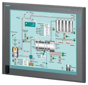
בקרת תהליך ייצור על ידי מערכות בקרה ואוטומציה מתקדמות על ידי חברת סמארט לוג'יק.
להלן מידע אודות ולידציה, בקרת תהליכים תעשייתיים, בקרה ואוטומציה ועוד.
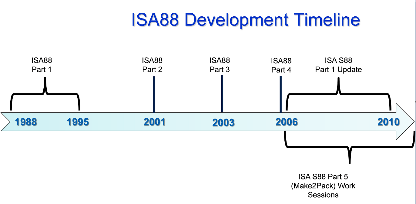
הקיצור S-88 מסמל את התקן ANSI/ISA-88 – S88. תקן זה מתייחס לבקרת אצווה Batch Control, ומהווה גישה תכנונית לתיאור ציוד ותהליך תכנון. תקן זה לא נועד לתוכנה בלבד; אלא משמש גם לתהליכים ידניים. התקן אושר ע"י ISA ב- 1995 ועודכן ב- 2010.
סמארטלוג'יק מתמחה בתכנון תהליך בתקן S-88 מאפיון Control-Modules דרך Equipment modules וכלה בפאזות תהליכיות. שירותי החברה מסתמכים על ידע וניסיון רב בעבודה עם מערכות מים, RO ,CIP, מזקקות, מערכות HVAC ,Utilities, ומודולים מוכנים סטנדרט S-88 שפיתחנו עבור מערכות אלו.
International Society of Automation – ISA הינה אגודה טכנית ללא מטרות רווח, מיועדת למהנדסים, טכנאים, אנשי עסקים, מחנכים וסטודנטים, שעובדים, לומדים או מעוניינים באוטומציה תעשייתית ועיסוקים מקושרים לנושא, כגון מכשור.
ISA כוללת תחומים טכניים והנדסיים רבים, והינה אחת מהארגונים המובילים בעולם בקביעת סטנדרטים והדרכת אנשי מקצוע בתעשייה בנושא אוטומציה.
American National Standards Institute – ANSI הינה ארגון פרטי ללא מטרות רווח שמפקח על פיתוח תקנים מוסכמים בהתנדבות, עבור מוצרים, שירותים, תהליכים, מערכות וכוח אדם בארה"ב. ארגון זה גם מתאם בין תקנים אמריקאים ובינלאומיים, כך שמוצרים אמריקאים יוכלו להיות משווקים בכל העולם.
ANSI מאשרת תקנים מפותחים ע"י נציגים של ארגונים, סוכנויות ממשלתיות, קבוצות צרכנים, חברות, וגופים אחרים. תקנים אלו מבטיחים שתכונות וביצועי המוצרים הם אחידים, שהציבור משתמש באותם הגדרות ומינוחים, ושהמוצרים נבדקים באותה צורה. ANSI גם מספקת אישורים לארגונים שמסמיכים מוצרים או כוח אדם בהתאם לדרישות מוגדרות בתקנים בינלאומיים.
כללי
ועדת ANSI/ISA-88 פרסמה סדרת תקנים בנושא בקרת אצווה במערכות אוטומציה תעשייתיות.
תקן ,ANSI/ISA-88.00.01-2010, Batch Control Part 1: Models and Terminology מספק דגמים ומינוחים תקניים (סטנדרטיים) להגדרת דרישות בקרה עבור מפעלים שמייצרים אצוות.
תקן ANSI/ISA-88.00.02-2001, Batch Control Part 2: Data Structures and Guidelines for Languages, מגדיר דגמים של נתונים(data) שמתארים בקרת אצווה כפי שהיא משמשת במערכות אוטומציה תעשייתיות, מבני נתונים שמאפשרים קידום תקשורות פנימיות וגם בין יישומי בקרת אצווה שונים, והנחיות לגבי שפות שמייצגות מתכונים (recipes).
תקן ANSI/ISA-88.00.03-2003, Batch Control Part 3: General and Site Recipe Models and Representation, מגדיר דגם עבור מתכונים כלליים ומקומיים; פעילויות שמתארות את שימוש המתכונים הכלליים והמקומיים במסגרת חברה אחת ובין חברות שונות; ייצוג מתכונים כלליים ומקומיים; ודגם נתוני מתכונים כלליים ומקומיים.
תקן ANSI/ISA-88.00.04-2006, Batch Control Part 4: Batch Production Records, מספק הגדרה מפורטת עבור רישומי ייצור אצוות, וקובע דגם ייחוס לפיתוח אפליקציות לאחסנת ו/או המרת רישומי ייצור אצוות. יישומים מבוססים על תקן זה מאפשרים אחזור, ניתוח ודיווח של רישומי ייצור אצוות נבחרים.
S-88 מיועד לאספקת תקנים והרגלי עבודה מומלצים לתכנון והגדרת מערכות בקרת אצווה בתעשיות עם בקרת תהליכים.
S88 מספק הנחיות לפיתוח וספציפיקציות של מערכות בקרת אצווה. הנחיות אלו גם מבוססות על תקנים והרגלי עבודה מומלצים ע"י ISA וארגונים אחרים, וגם משלים את התקנים וההמלצות הנ"ל. הנושאים שיילקחו בחשבון להכללתם ע"י הועדה הם:
סמארטלוג'יק מבצעת פרויקטי אוטומציה ובקרה מודולארית למתקני יצור תוך שימוש בתקן S-88
As I've promised on my last post – Good Automated Manufacturing Practice (GAMP) Test Execution – part 1 I will now continue to elaborate on the execution of a test using automated (computerized) test tools. These tools should be conducted in accordance with the Test Plan or Strategy. This should require that all automated tools used to test GxP systems have been subjected to assessment and appropriate validation prior to their use, in order to establish s a high degree of assurance that they will perform as intended, and return accurate and secure results.
Before discussing the benefits and use of automated test tools, it is useful to describe the difference between a computerized test management tool and automated testing.
A computerized test management tool facilitates the task of Test Case and Test Script authoring, review and approval (pre and post execution), test execution, and test deviation management. This is accomplished using workflow enabled processes, electronic test artifact management (i.e., Test Cases, Test Scripts, Deviation Reports), and possibly electronic signatures.
However, even with computerized test management, the actual test execution is performed by the tester, even when this task is aided by the presentation of on-screen test scripts and electronic capture of test evidence. The tester must still manually follow the test steps, provide inputs to the system under test, and record the test evidence.
With automated test execution, the computerized test tool also executes the actual test and records the test evidence. This can significantly reduce the test execution time. Because most automated test execution is based upon initial manual test execution (where the tool often 'records' the manual actions of the tester), automated testing is most often used when executing tests during a second test cycle and is well sited to regression testing.
When planned properly, automating the test activities can bring considerable benefits within the project life cycle. However, if poorly planned, computer based tools and test automation may be difficult, complex, and time consuming task, with little or no return on investment.
Computerized test management tools can significantly reduce the amount of paper used during testing and provide helpful test management support. This includes the ability to report on the test activities status and facilitate test activities using workflow. In most large testing projects, the use of such tool can reduce testing timescales.
Not every aspect of a computerized system can be automatically tested. A key factor in the successful use of such tools is the early identification of the types of tests that should be automated, and the types of tests to be executed manually.
While computerized test management tools and automated testing can both provide benefits, they should be considered separately. Some project may benefit from the use of computerized test management tools, but may derive little benefits using automated test tools.
Before deciding on the usefulness of computerized test management and automated test tools, the following points should be considered:
Will the tools be used in a single project or more broadly within the organization? Typically in a large project or organization, a wide use is necessary to provide return on investment.
How many test cycles are typically executed, and how much regression testing is required? This will help determine the need for automated testing.
Will the tool be used by a dedicated test team, or in all projects? This has an impact on on-going administration and training requirements.
The use of computerized test management and automated test tools need to be regarded as a SW development activity that has its own life cycle. These tools will have their own implementation and validation life cycle. This will place additional requirements on the test team, particularly in terms of the skills required by test script developers.
The use of these tools is only effective if supported by adequate processes and if the staff has the necessary skills to use the tools effectively. The usability of a test tool is significantly enhanced if it is application-interdependent (i.e., used to test multiple application).
Easy maintenance of a test suite is crucial for a successful implementation of an automated test tool.
Automated test tools which include a version and configuration management can significantly improve the effectiveness and efficiency of retesting.
Different test management and automated test tools are used In the IT industry, and the architecture of the application under test often determines the most suited tool. Most tools are purchased as configurable off-the-shelf SW packages, and the test team then configures the package locally to meet the particular usage required.
Before acquiring computerized test management tools or automated test tools, it is important that an organization understands and defines the requirements and form of use.
Test management tools may be classified into four general types:
General computerized test management tools
Developer-oriented tools
Functional test tools
Load and performance related tools
General Computerized Test Management Tools
Manage testing across the project.
Facilitates authoring, review and approval of Test Cases and Test Scripts, often using workflow and electronic signatures.
Allow developers, testers and project managers to track tests being run on various applications.
Trace tests back to their original requirements.
Summaries the defects found during the testing process.
The test management tools help to determine whether changes need to be made to the automated test tools themselves, as a result of changes to the applications being tested. However, they do not provide the facility to automate test execution.
Other tools do provide automated test execution (often integrated into the test management tools). The type of automated test execution tool depends to a large extent on the type of SW application under test and the type of test being executed. Three such tools are presented below
Developer-Oriented Tools
Are used in unit, component and module testing to address issues such as memory leaks or other early performance problems.
Are used to test specific pieces of the developer's application code independent of other units of code within the SW application.
May incorporate capture-replay utilities, which run sample tests against working versions of a program, capturing the activity it generates. During the playback phase, developers can see whether or not they are generating the results they expected.
Are particularly useful in testing large applications where different developers are working on different parts of the application.
Test that the code being developed is acting as expected.
Often contain keyword or table driven execution engines, which allow the development and execution of repeatable tests.
Often have scripting capabilities, allowing testers to modify their scripts to test additional items.
Can often be linked back to other packages providing Requirements Capture and Tracking capabilities, thus facilitating comprehensive requirements traceability.
Are particularly useful to test what happens to the code when multiple users access the application simultaneously, or transactions are required to be submitted, or responses are achieved in tight deadlines that manual testing could not reproduce accurately or consistently.
Are particularly useful for critical web based applications, because it is often difficult to predict the volatility of load change. Tools developed for this type of work can often drill down to lower levels of the code to find out where the bottlenecks are, and what is causing any delays.
These tools can also be valuable when testing the application scalability.
Functional Test Tool
Load and Performance Related Tools
Use of Computerized Test Management and Automated Test Tools
As stated above, Computerized Test Management Tools and Automated Test Tools can prove advantageous on large projects or within an organization. However, the use of such tools will require:
Use of testing procedures (SOPs or Work Instructions) for the activities supported by the tools, such as:
Test Case / Test Script authoring
Test Case / Test Script review and approval
Test execution
Test result review and approval
Test defect reporting
Test defect categorization
Test defect disposition
Test defect closure
Other activities, such as test planning and test status reporting, are less critical from a regulatory perspective and will not require formal procedures.
Users of the test tools that are properly trained in the use of the procedures.
Administration of the tool, including:
Configuration of the tool
Creation of test projects
Administration of users
Support and maintenance activities (backup and restore, capacity planning and performance monitoring, etc.)
Smartlogic ,when implementing test tools, initially defines the test processes to be supported by the tool(s). These test processes should comply with the testing good practices defined by GAMP, and the specific test policies and processes of the owning organization, which should define the requirements for using this tool(s).
All users of the test tools should be trained, not only in the use of the tools, but also in good testing practices.
When using test tools, clear user roles and responsibilities should be defined for each test process. Appropriate technical or procedural access restrictions should ensure that only authorized users are allowed to fulfill a defined role, and that the independence of the test process can be verified and enforced.
When used, computerized test management tools and automated test execution tools should provide the same level of test data integrity as an equivalent paper based process.
All these conditions and requirements can be facilitated through the use of features such as:
Role based authorities and user restrictions
Use of workflow to enforce test processes
Use of electronic or digital signatures
Secure, computer generated audit trails
Verification of Computerized Test Management and Automated Test Tools
The need to assure the security, integrity and availability of test data requires the appropriate selection and verification of the automated test tools (refer to GAMP 4, Appendix M4, section 4 for further details). Because such tools usually have only an indirect impact on product quality, they are considered low risk priority and do not require a detailed a lengthy validation process.
The verification of a computerized test management or automated test tools should focus on demonstrating that the tools are fit for purpose as far as critical requirements are concerned. The critical requirements that should form the basis of the tool verification are:
Security of the test data, facilitated by role based authorities and user restrictions, the use of electronic or digital signatures, and the use of secure, computer generated audit trails. Where the tools do not provide these features, the verification of the tool(s) should focus on establishing such security using logical or physical security controls, procedural controls and paper based audit trails.
Ability of the test tool to enforce defined test processes using workflow or equivalent controls. Where this is not possible, the verification of the tool(s) should focus on the ability of the tool to provide audit trail evidence of the test processes.
The scope of the verification activities may be scaled based upon risk, and should take into account the track record of the supplier and tools in the life sciences.
Test data managed within test tools would not usually be determined to be an electronic record within the scope of predicate rules, and the use of electronic or digital signatures would not usually be determined within the scope of predicate rules, so that the requirements of regulations such as 21 CFR Part 11 would not usually apply.
However, there may be cases where the SW or application tested using such tools is of greater regulatory significance, for example, where the SW or application is defined as a medical device or part of it. In these cases, a more formal validation of the test may be required:
The test record may also be determined to be an electronic record (i.e., an acceptance record under 21 CFR Part 820 Subpart H – Acceptance Activities).
Any associated signatures may be determined to be electronic or digital signatures (i.e., under 21 CFR Part 820.80).
The test management tools may need to comply with the requirements of 21 CFR Part 11, and other regulator guidance in electronic records and digital signatures
This articular is the third part of our review about PLCs. After PLCs Functionality&Features and PLCs Topic – part 1 that covers the subjects of Scan Time, System Scale, User interface & Communications, this part is about PLCs Programming, Digital and Analog Signals & PLC Advantages.
PLC– Programming
PLC programs are typically written in a special application on a PC, then downloaded by a direct-connection cable or over a network to the PLC. The program is stored in the PLC either in battery-backed-up RAM or some other non-volatile flash memory.
IEC 61131-3 defines several programming languages for programmable control systems, which emphasize logical organization of operations.
While the fundamental concepts of PLC programming are common to all manufacturers, differences in I/O addressing, memory organization and instruction sets mean that PLC programs are never perfectly interchangeable between different makers. Even within the same product line of a single manufacturer, different models may not be directly compatible.
PLC – Digital and Analog Signals
Digital or discrete signals behave as binary switches, yielding simply an On or Off signal (1 or 0, True or False, respectively). Push buttons, limit switches, and photoelectric sensors are examples of devices providing a discrete signal. Discrete signals are sent using either voltage or current, where a specific range is designated as On and another as Off. For example, a PLC might use 24 V DC I/O, with values above 22 V DC representing On, values below 2VDC representing Off, and intermediate values undefined. Analog signals are like volume controls, with a range of values between zero and full-scale. These are typically interpreted as integer values (counts) by the PLC, with various ranges of accuracy depending on the device and the number of bits available to store the data. Pressure, temperature, flow, and weight are often represented by analog signals. Analog signals can use voltage or with a magnitude proportional to the value of the process signal. Current inputs are less sensitive to electrical noise (i.e. from welders or electric motor starts) than voltage inputs.
PLC Advantages Relative to Other Control Systems
PLCs are well adapted to a range of automation tasks. These are typically industrial processes in manufacturing where the cost of developing and maintaining the automation system is high relative to the total cost of the automation, and where changes to the system would be expected during its operational life. PLCs contain input and output devices compatible with industrial pilot devices and controls; little electrical design is required, and the design problem centers on expressing the desired sequence of operations. PLC applications are typically highly customized systems, so the cost of a packaged PLC is low compared to the cost of a specific custom-built controller design.
Here are some examples of the PLCs used by smartlogic: 6XV1830-0EH10, 6ES7131-4BF00-0AA0,6ES7193-4CA40-0AA0,6ES7134-4GD00-0AB0,6ES7193-4CA40-0AA0, 6ES7138-4CA01-0AA0,6ES7193-4CC20-0AA0, 6ES7590-1AB60-0AA0, 6ES7511-1AK00-0AB0, 6ES7954-8LP01-0AA0,6ES7155-6AU00-0BN0
A Programmable Logic Controller – PLC is a digital computer used for automation of electromechanical processes, such as control of machinery on factory assembly lines. Unlike general-purpose computers, the PLC is designed for multiple inputs and output arrangements, extended temperature ranges, immunity to electrical noise, and resistance to vibration and impact. Programs to control machine operation are typically stored in battery-backed-up or non-volatile memory. A PLC is an example of a hard real time system since output results must be produced in response to input conditions within a limited time, otherwise unintended operation will result.
PLCs are usually programmed using application software (SW) on personal computers (PCs). The PC is connected to the PLC through Ethernet, RS-232, RS-485 or RS-422 cabling. Most PLCs used by smartlogic when designing an automation and control systems are the Siemens PLC and Allen Bradley's.The programming SW allows entry and editing of the ladder-style logic. Generally the SW provides functions for debugging and troubleshooting the PLC software, for example, by highlighting portions of the logic to show current status during operation or via simulation. The SW will upload and download the PLC program, for backup and restoration purposes.
The functionality of the PLC includes sequential relay control, motion control, process control, distributed control systems and networking. The data handling, storage, processing power and communication capabilities of some modern PLCs are approximately equivalent to desktop computers.
The PLC unit consists of separate elements, such as power supply, controller, relay units for in- and output
The main difference from other computers is that PLCs are armored for severe conditions (such as dust, moisture, heat, cold) and have the facility for extensive input/output (I/O) arrangements. These connect the PLC to sensors and actuators. PLCs read limit switches, analog process variables (such as temperature and pressure), and the positions of complex positioning systems. On the actuator side, PLCs operate electric motors, pneumatic or hydraulic cylinders, magnetic relays, solenoids, or analog outputs. The input/output arrangements may be built into a simple PLC, or the PLC may have external I/O modules attached to a computer network that plugs into the PLC.
Here are some examples of the PLCs used by Smartlogic: 6XV1830-0EH10, 6ES7131-4BF00-0AA0, 6ES7193-4CA40-0AA0, 6ES7134-4GD00-0AB0, 6ES7193-4CA40-0AA0, 6ES7138-4CA01-0AA0, 6ES7193-4CC20-0AA0, 6ES7590-1AB60-0AA0, 6ES7511-1AK00-0AB0, 6ES7954-8LP01-0AA0, 6ES7155-6AU00-0BN0, 1746-NO4V, 1769-L16ER-BB1B
מערכת בקרה תעשייתית היא מונח כללי שמתייחס לסוגים שונים של מערכות בקרה שמשמשים בייצור תעשייתי, כולל: מערכת בקרה לפיקוח והשגת מידע -Supervisory Control and Data Acquisition – SCADA, מערכת בקרה מבוזרת – DCS – Distributed Control System – , וקונפיגורציות של מערכות בקרה קטנות יותר כגון בקרים עם לוגיקה שניתנת לתכנות – Programmable Logic Controllers -PLCs שנמצאים לעתים קרובות במערכים תעשייתיים ותשתיות קריטיות.
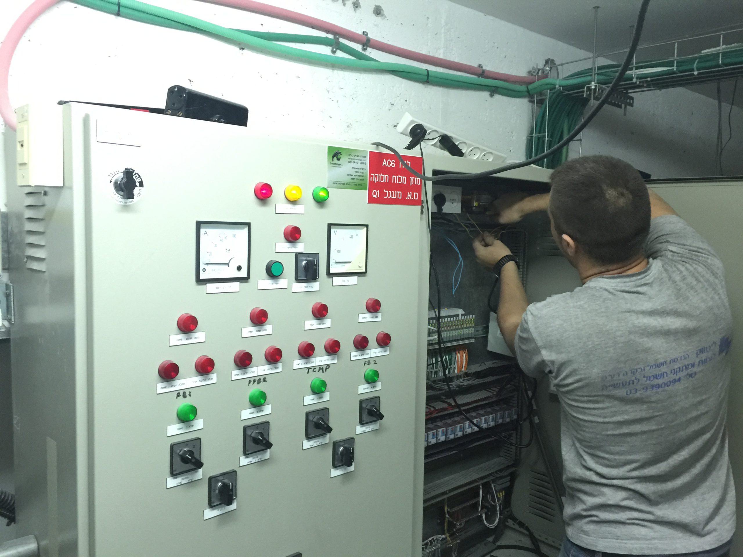
.מערכות בקרה תעשייתיות משמשות בד"כ בתעשיות שמייצרות או מספקות מוצרים חשמליים, מים, נפט, גז, ומידע. סמארטלוג'יק מתמחה באוטומציה ובקרה, בתכנון,התקנה ותחזוק מערכות אלו
Supervisory Control and Data Acquisition – SCADA – System
מערכת בקרה מסוג זה פועלת עם אותות מקודדים שעוברים דרך ערוצי תקשורת לאספקת בקרה על ציוד מרוחק (בד"כ ערוץ תקשורת אחד עבור תחנה מרוחקת אחת). מערכת הבקרה יכולה להשתלב עם מערכת להשגת מידע ע"י הוספת שימוש באותות מקודדות על ערוצי תקשורת, להשגת מידע על הסטאטוס של הציוד המרוחק לצורך תצוגה או הקלטה.
מערכות בקרה אלו מבוססות על מערכות ממוחשבות שמנטרות ומבקרות תהליכים תעשייתיים. מערכות מסוג SCADA נבדלות היסטורית ממערכות תעשייתיות אחרות עקב תהליכים בקנה-מידה גדולים שכוללים אתרים רבים מפוזרים במרחקים גדולים.
Distributed Control System- DCS
מערכת בקרה מסוג זה משמשת לבקרת תהליכים תעשייתיים כגון ייצור חשמל, זיקוק נפט וגז, אספקת מי שתייה וטיפול במי ביוב, וייצור מוצרים כימיים, מוצרי אוכל ומכוניות. מערכות מסוג DCS משתלבות במערכי בקרה הכוללים פיקוח על תת-מערכות משולבות אחראיות על בקרת ציוד בתהליכים מקומיים.
בקרת מוצרים ותהליכים מושגת בד"כ בעזרת חוגי בקרה עם הזנה אחורה – feed-back control loop – או הזנה קדימה – feed-forward control loop, כך שתנאי המוצר או התהליך נשמרות באופן אוטומטי תוך טווח מוגדר סביב ערך נתון (set point). השגת תנאי מוצר או תהליך במסגרת טווחים מוגדרים אפשרית רק בעזרת בקרים מסוימים הניתנים לתכנות.
בקר מסוג זה מספק בקרה של פעולות לוגיות בוליאניות (Boolean), קוצבי זמן, ותהליכים רציפים (בדגמים מסוימים). יחסי ההגדלה הפרופורציוניים, אינטגרליים ו/או דיפרנציאליים של הבקר בתהליכים רציפים ניתנים לכוונון כדי להשיג את דיוק הטווח מוגדר וכן את מהירות התיקון העצמי במקרה של תקלות בתהליכים. בקרים מסוג PLC משמשים בהרחבה בתעשיות מבוססות על תהליכים. בקרים אלו מתבססים על מחשבים שמבקרים ציוד ותהליכים תעשייתיים. אם כי בקרים מסוג PLC מסוגלים לבקר מרכיבי מערכת שפועלים בעזרת מערכות מסוג SCADA ו- DCS, הם גם באופן תדיר משמשים כרכיבים עיקריים בקונפיגורציות של מערכות בקרה קטנות יותר. הם משמשים גם להענקת בקרה רגולטורית של תהליכים דיסקרטיים , כגון קווי הרכבת מכוניות, ובנוסף משמשים בכמעט כל תהליכי הייצור התעשייתיים.
After a test is written, reviewed, perhaps rewritten, and finally approved, it is then ready for execution.
Before commencing GAMP tests using individual Test Cases or Test Scripts, pre-requisites for the test phase should first be verified and recorded. For example:
Manual Test Execution
Tests should be carried out as follows:
Possible actions for failed tests and incidents are:
The review group should decide which course of action to take and what retesting is required, and document the justification for the action(s). In my next post I will elaborate more on: Automated Test Execution (and Computerized Test Management Tools).
משתמשים במונח ולידציה לתיאור פעילות הכוללת הכנת הוכחה מתועדת, שמעניקה מידה גבוהה של ביטחון, שתהליך ספציפי יפיק באופן קונסיסטנטי תוצאה שעומדת בספציפיקציות ותכונות איכות מוגדרות מראש
ולידציה מקושרת בד"כ עם מתקן יצור של מוצר שאיכותו עשויה להשפיע על בריאות הציבור, ולכן היא מיועדת לצמצם למינימום את אפשרויות הסיכון הפוטנציאליות שעלולות להשפיע לרעה על איכות המוצר
תהליך הולידציה חייב לעמוד בתקנים של המנהל האמריקאי FDA. התקנים הרלוונטיים ביותר לתהליך הולידציה הם:
• Good Manufacturing Practice – GMP
• Current Good Manufacturing Practice – cGMP
• Good Automated Manufacturing Practice – AMP.
במונח GxP משתמשים יותר בחופשיות בז'רגון הולידציה בהתייחסות לאוסף כללים מנחים.
cGMP הוא הדוגמה הנפוצה ביותר של GxP. עמידה בתקני cGMP מבטיחה אחידות, עוצמה, איכות וטוהר של מוצרים רפואיים ע"י דרישות מיצרני התרופות לבקרה הולמת על תהליכי היצור שלהם.
תקנים נוספים של ה- FDA הרלוונטיים לתהליך הולידציה הם:
• Good Laboratory Practice – GLP.
• Good Clinical Practice – GCP.
תהליך ולידציה כולל תכנון, התקנת והפעלת מערכת ניטור ובקרה במתקו יצור, וכמו כן, תכנון וביצוע תהליכי בדיקה כדי לוודא שמערכת הניטור והבקרה עומדת בסטנדרטים של ה- FDA.
תיעוד ולידציה הינו חלק של תהליך הולידציה שמכיל רישומים כתובים ו/או אלקטרוניים ביחס להתקנה והפעלת מערכת הניטור והבקרה, וביחס לבדיקות המתאימות של אותה מערכת.
הרישומים האלקטרוניים נדרשים בד"כ לעמוד בדרישות FDA שמתייחסות להיקף וישום של התקן
Part 11 of Title 21 of the Code of Federal Regulations; Electronic Records; Electronic Signatures – 21 CFR Part 11.
רישומים אלקטרוניים – Electronic Records יכולים להכיל כל שילוב של מלל, גרפיקה, אודיו, צילומים, או כל מידע אחר המוצג באופן אלקטרוני, כאשר אלו מיוצרים, משתנים, מתוחזקים, מתויקים, מוחזרים ומופצים ע"י מערכת מחשבים.
חתימות אלקטרוניות – Electronic Signatures יכולות להכיל אוסף של כל סמל או סדרת סמלים מבוצעים, מאומצים או מאושרים ע"י גורם שמחויב חוקית באופן שווה ערך לחתימתו בכתב.
משתמשים ברישומים וחתימות אלקטרוניים בד"כ במערכות סגורות, בהן הגישה למערכת מבוקרת ע"י צוות אחראי על התכנים של הרישומים האלקטרוניים.
תיקי ולידציה מכילים באופן כללי שני סוגי מסמכים:
• מסמכים קשורים לתכנון, התקנת והפעלת מערכת הניטור והבקרה:
– ספציפיקציה נדרשת ע"י המשתמש User Requirements Specification – URS
– ספציפיקציה של דרישות פונקציונאליות Functional Requirements Specification -FRS
– ספציפיקציה של תכנון פונקציונאלי Functional Design Specification – FDS
– ספציפיקציה של תכנון חומרה Hardware Design Specification – HDS
– ספציפיקציה של תכנון תוכנה Software Design Specification – SDS
– שרטוט צנרת ומכשור Piping and Instrument Drawing – P&ID
– רשימת כניסות/יציאות Input/Output (I/O) List
• מסמכים שכוללים את תהליכי הבדיקות:
– פרוטוקול קווליפיקצית התקנה Installation Qualification (IQ) Protocol
– פרוטוקול קווליפיקצית פעולה Operation Qualification (OQ) Protocol
– פרוטוקול קווליפיקצית ביצוע Performance Qualification (PQ) Protocol
האחריות לכתיבת ואישור המסמכים משותפת בפועל למשתמש, שמפעיל את מתקן היצור, והספק, שמספק את מערכת הניטור והבקרה להבטחת הפעולה הנכונה של המתקן.
תיקי ולידציה כולל בנוסף חוברות הדרכה / חוברות נתונים / ברושורים של רכיבי המערכת העיקריים לתמיכת משימות הפעולה והתחזוקה של המשתמש.
לחץ כאן למדריך מפורט של היצרן:
התקן מכאן במחשב .Net Framework 4